
Ion guiding device and related method

a technology of guiding device and guiding method, which is applied in the direction of electric discharge tube particle separator tube details, etc., can solve the problems of reducing the sensitivity of instruments, axial transmission of ions, and ion guiding device takes a long period of time to pass through, so as to achieve effective ion transmission speed and reduce overall length of instruments, the effect of increasing the signal-to-noise ratio of the guiding devi

Active Publication Date: 2021-05-06
SHIMADZU CORP
View PDF0 Cites 1 Cited by
  • Summary
  • Abstract
  • Description
  • Claims
  • Application Information

AI Technical Summary

Benefits of technology

The ion guiding device and method described in this patent have several benefits: 1. It allows for faster ion transmission and easier off-axis ion optics, which improves the ion guiding device's signal-to-noise ratio and reduces the overall instrument length. 2. It has a simple structure and easy operation.

Problems solved by technology

However, such devices have a common disadvantage that the axial transmission of ions is merely driven by the initial kinetic energy of the ions or an axial airflow due to the lack of an axial driving electric field.
However, generally, under a gas pressure between 1 Pa and 10 Pa, it often takes a long period of time for ions to pass through an ion guiding device.
In addition, if the ions dwell in the ion guiding device for a too long time, not only the analysis speed of instruments will be influenced, but also a certain ion loss will be caused to decrease the sensitivity of the instruments.
Moreover, due to the lack of axial electric field for driving, such ion guiding devices are generally limited to use a linear structure.
Consequently, the overall length of the instruments is relatively long.
In addition, the ion acceptance area and the ion focusing capability of device such as quadrupole rods are related to the radius of the RF field of the devices, and are mutually restricted.
However, there are still some new challenges when the curved ion guiding device is used as a collision cell.
However, when the kinetic energy of the parent ions is too high, the parent ions are very likely to escape from the RF field and thus directly hit the electrodes to result in ion loss.
Due to the limitation of the breakdown voltage in the vacuum environment, it is unable to enhance the confinement of ions only by increasing the RF voltage.
Although this method may properly solve the problems caused by the high-speed injection of the ions, compromise is made to a certain extent with respect to the issue of shortening the length of the instrument.
Moreover, the length of the ion guiding device itself also becomes longer.
Although this device may properly solve the above problems, either the device is very complicated in structure and difficult to process or the axial driving electric field and the radial deflection electric field are coupled together and difficult to control.
As a result, the comprehensive performance is affected to a certain extent.
However, the flux of ions is also reduced as the conductance of gas flow is limited.
However, this device is still limited by many problems.
For example, the gas pressure shall not be too high, and it is unable to provide an axial driving electrical field as well as a radial deflection electric field.

Method used


Image

  • Ion guiding device and related method
  • Ion guiding device and related method
  • Ion guiding device and related method

Examples


embodiment 1

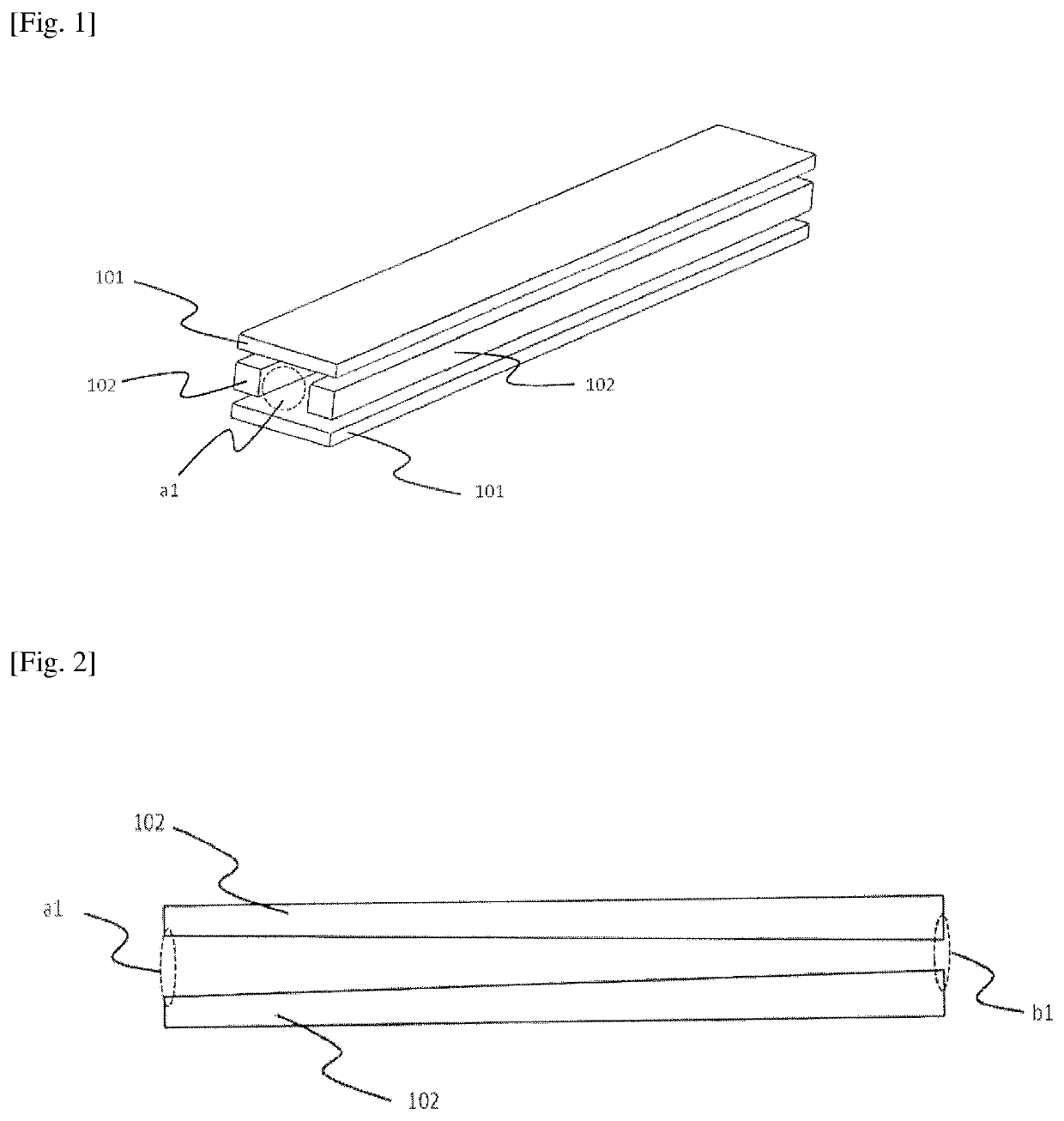
[0064]As shown in FIG. 1, in Embodiment 1, the ion guiding device is of a linear structure, including a first electrode assembly 101, a second electrode assembly 102 and a power supply device (not shown). Wherein, the first electrode assembly 101 includes a pair of parallel electrode units arranged along a spatial axis, and the second electrode assembly 102 includes at least two non-parallel electrode units arranged in a parallel plane between the parallel electrode units along the spatial axis. Hence, the first electrode assembly 101 and the second electrode assembly 102 form an ion transmission channel along the spatial axis, with a larger ion inlet a1 and a smaller ion outlet b1, as shown in FIG. 2. In this embodiment, as the second electrode assembly 102, square rod electrodes or plate electrodes are used, and the second electrode assembly 102 has a rectangular cross-section.

[0065]The power supply device applies RF voltages with the same amplitude and frequency and opposite pola...

embodiment 2

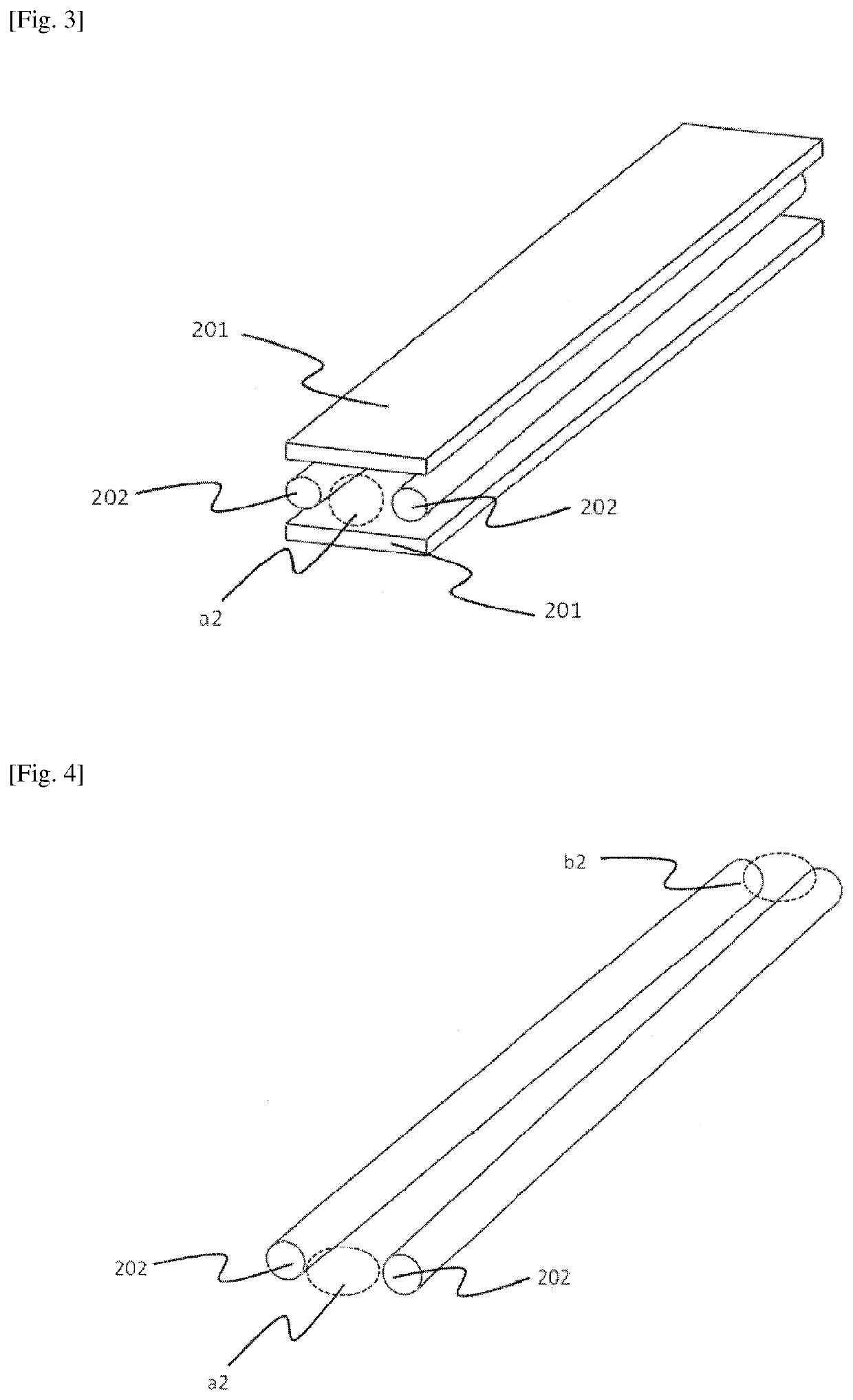
[0070]As shown in FIGS. 3 and 4, a main difference between the ion guiding device in Embodiment 2 and the ion guiding device in Embodiment 1 lies in that, as the second electrode assembly 202, round rod electrodes are used. The implementation of the RF voltages and the DC voltages in this embodiment is basically same as that in Embodiment 1. The advantage of using round rod electrodes is that the field form of the quadrupole field is better, so it is advantageous for confining ions in the directions perpendicular to the spatial axis. Similarly, since the ion transmission channel has a larger ion inlet a2 and a smaller ion outlet b2, a large ion acceptance area is obtained, and the focusing effect of the ions is also excellent.

[0071]It is to be noted that, as the first electrode assembly 202, round rod electrodes may also be used to further improve its performance. However, the processing difficulty will be increased.

embodiment 3

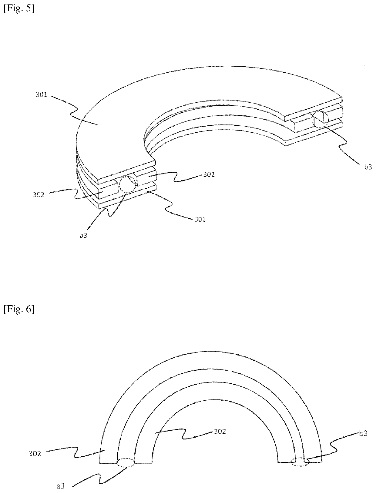
[0072]The spatial axis may be a straight axis, a curved axis or a combination thereof. As shown in FIG. 5, in Embodiment 3, the spatial axis of the ion guiding device of the present invention is a curved axis of 180 degrees. Wherein, as the first electrode assembly 301, curved plate electrodes of 180 degrees are used. As shown in FIG. 6, the second electrode assembly 302 includes two arc electrode units which are bent 180 degrees. The two arc electrode units are not of a coaxial structure, and the spacing between the two arc electrode units decreases gradually from an ion inlet a3 to an ion outlet b3 in the direction of the spatial axis. Therefore, the cross-sectional area of the ion transmission channel formed in the curved ion guiding device also changes in the direction of the spatial axis. After the RF voltages and DC voltages are applied in a way similar to that in Embodiment 1, a RF electric field perpendicular to the spatial axis may also be formed to confine ions, and an axi...


PUM


Abstract

The ion guiding device comprises a first electrode assembly comprising two parallel electrode units arranged along a spatial axis; a second electrode assembly comprising at least two non-parallel electrode units arranged in a plane between the parallel electrode units along the spatial axis, wherein a space enclosed by the first electrode assembly and second electrode assembly forms an ion transmission channel along the spatial axis; and, a power supply device, which is configured to apply RF voltages with different polarities to the first electrode assembly and the second electrode assembly to generate a RF electric field in the directions perpendicular to the spatial axis to confine ions, and separately apply DC voltages to the first electrode assembly and the second electrode assembly to generate a certain DC voltage difference, to generate a DC electric field along the spatial axis to control the movement of ions.

Description

CROSS-REFERENCE TO RELATED PATENT APPLICATIONS[0001]This application is a U.S. national stage entry of PCT Application Serial No. PCT / JP2017 / 026695, filed Jul. 24, 2017, which claims priority to and the benefit of, Chinese Patent Application Serial No. 201710512171.6, filed Jun. 29, 2017, which are incorporated herein by reference in their entireties.FIELD OF THE INVENTION[0002]The present invention relates to the technical field of ion guiding, and in particular to an ion guiding device and an ion guiding method.BACKGROUND OF THE INVENTION[0003]In the prior arts, various ion guiding devices have been developed and widely applied in various mass spectrometers to realize the transmission, focusing and other manipulations of ions under various gas pressure conditions. Due to their advantages of simple structure, good ion focusing effect and so on, quadrupole ion guide becomes the most commonly used ion guiding device. Similarly, multipole ion guiding devices such as hexapole and octop...

Claims


Application Information

Patent Timeline
Patent Type & Authority Applications(United States)
IPC IPC(8): H01J49/06
CPCH01J49/063H01J49/062
Inventor CHENG, YUPENGZHANG, XIAOQIANGSUN, WENJIAN
Owner SHIMADZU CORP
Learn More