
Vehicle on-board charger for bi-directional charging of low/high voltage batteries

a technology for high-voltage batteries and chargers, which is applied in the direction of charging stations, battery/fuel cell control arrangements, transportation and packaging, etc., can solve the problems of affecting the structure, affecting the efficiency of the charging process, and affecting the charging effect of the battery, so as to achieve the effect of high efficiency

Active Publication Date: 2021-05-27
UNIV OF MARYLAND
View PDF0 Cites 52 Cited by
  • Summary
  • Abstract
  • Description
  • Claims
  • Application Information

AI Technical Summary

Benefits of technology

The present invention provides a compact, highly efficient, and bi-directional three-phase on-board charger system that can simultaneously charge both low and high voltage batteries in electric vehicles. The system integrates the functions of the on-board charger and auxiliary power module to achieve high efficiency with simultaneous charging. The control and power management strategy can manage the bi-directional power flow among three ports at different loading conditions, and the optimization strategy reduces peak current stress on MOSFET devices. An analytical model predicts the phase difference between the primary and secondary sides' currents of a charger's transformer to enhance synchronous rectification and minimize losses. The invention also eliminates the requirement for a high bandwidth secondary side current sensor.

Problems solved by technology

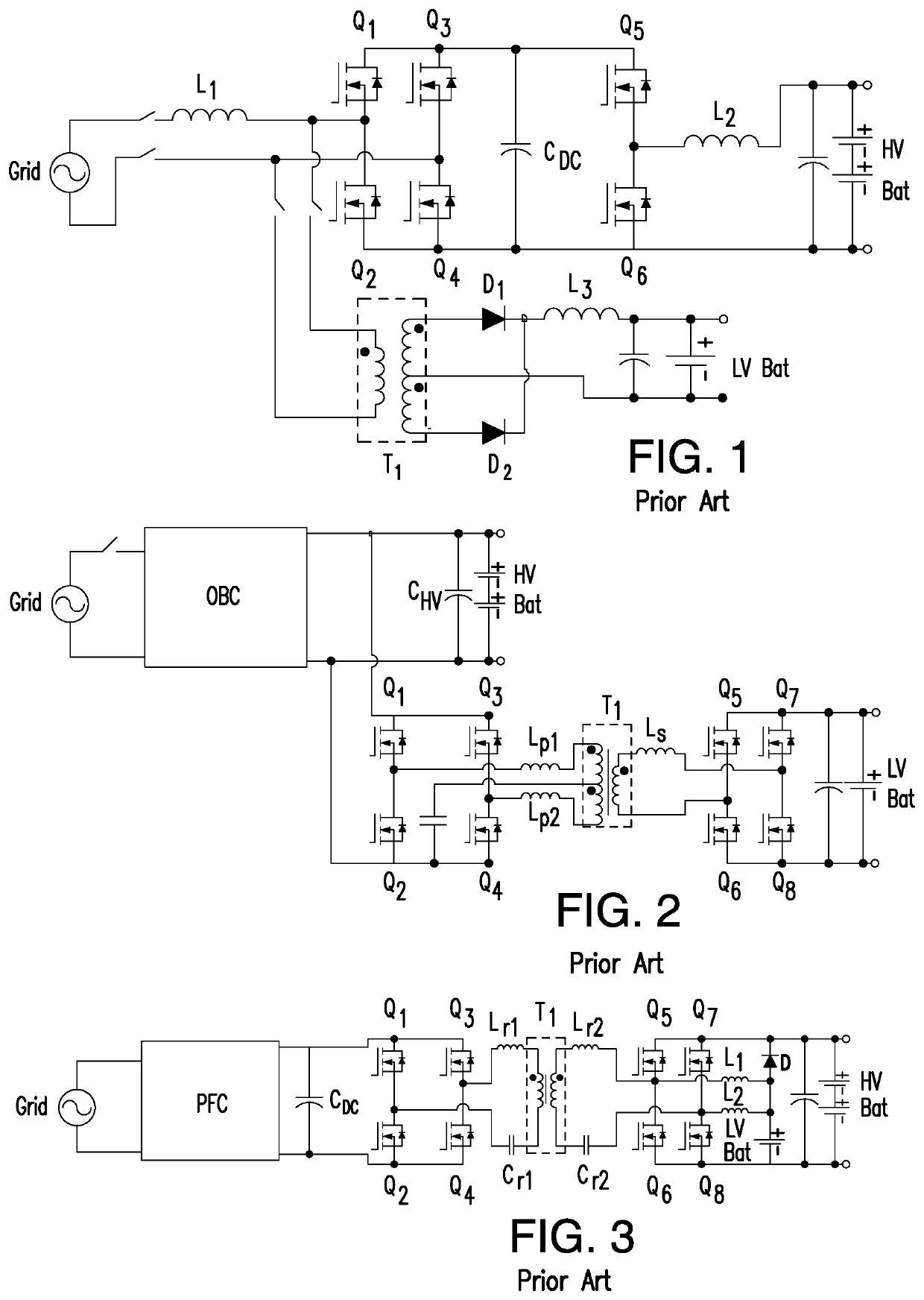
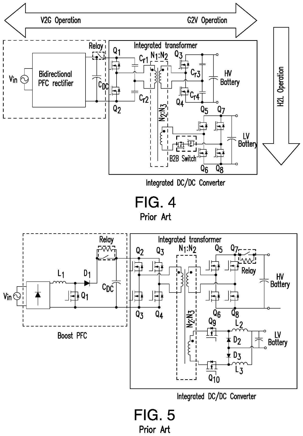
However, on-board chargers contribute to additional weight, volume and cost of the car.
Due to their charging power, limitations and slow charging process, it would take between 4-20 hours to fully charge a PEV battery using conventional on-board chargers.
This structural approach is detrimental due to additional or extra components, weight, and cost of the vehicle design.
Disadvantageously, in the grid-to-vehicle charging and vehicle-to-grid discharging modes, there is no isolation between the HV battery and the grid.
However, no isolation is provided therebetween.
However, disadvantageously, neither the circuit is integrated with any resonant converter, nor the operational principles of the circuit are made applicable to the resonant converter, which makes it inapplicable for LV charging applications.
Also, current ripple cancellation cannot be achieved by this topology, which further will require high output capacitance.
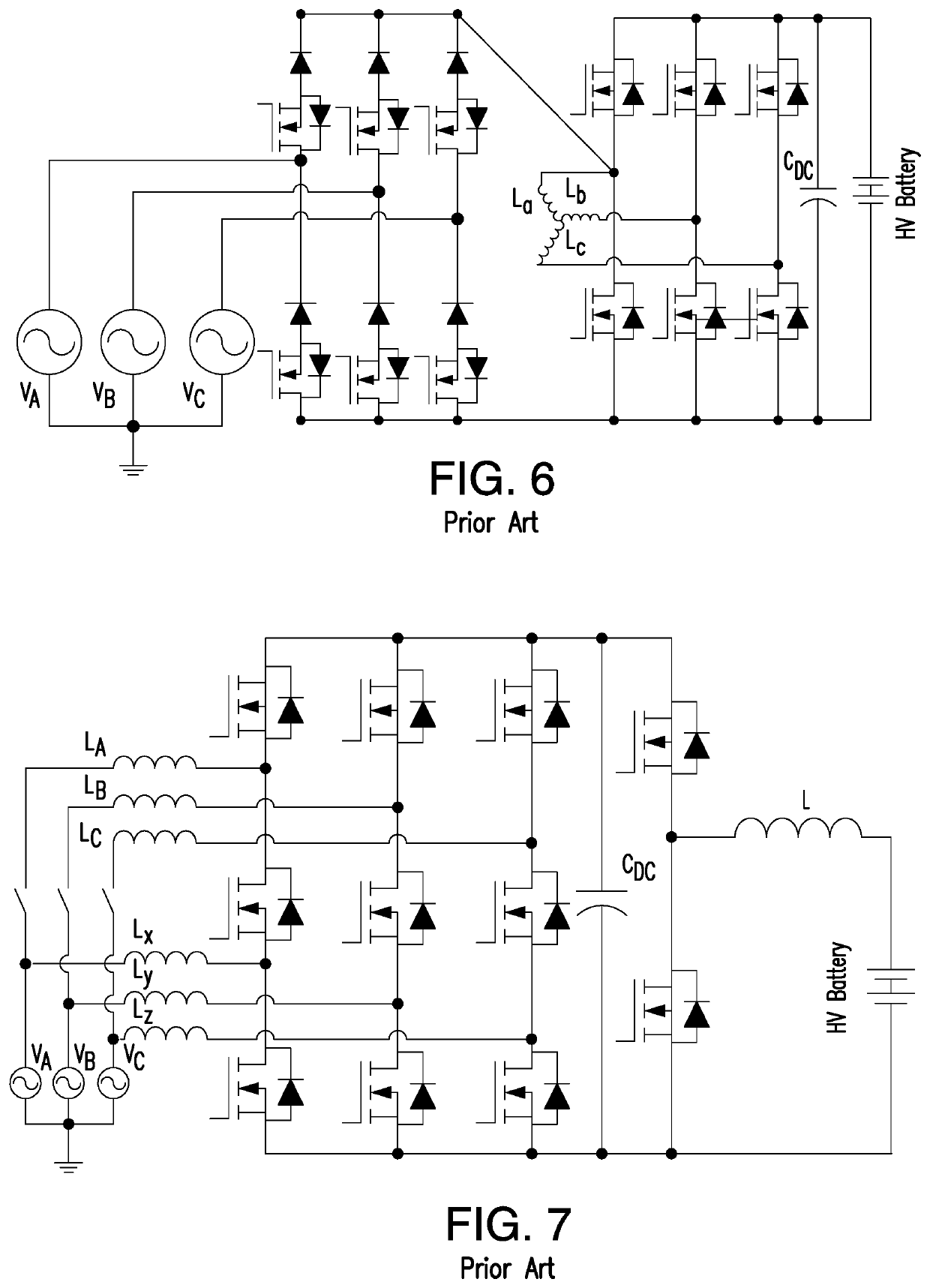
However, the inductor-based integration may negatively affect the longevity of the motor.
Disadvantageously, the midpoints of motor windings are not accessible for conventional propulsion system, which needs extra effort for adjustment.
This system does not provide isolation, i.e., if a galvanic isolation is mandatory, then either an electric machine with multiple isolated windings or an additional isolated DC-DC stage is required.
However, this topology is fundamentally for the DC / DC power conversion and is not aimed for the specific charging profile of EV battery, making it inapplicable for high-power integrated OBC applications.
However, due to large amounts of switches, complexity of this topology makes it unaffordable for high-power OBC application.

Method used


Image

  • Vehicle on-board charger for bi-directional charging of low/high voltage batteries
  • Vehicle on-board charger for bi-directional charging of low/high voltage batteries
  • Vehicle on-board charger for bi-directional charging of low/high voltage batteries

Examples


Embodiment Construction

[0133]Referring to FIGS. 10-38 the subject on-board charger system 10, includes an on-board charger (OBC) 12, also referred to herein as an on-board charging DC / DC converter, and an integrated transformer sub-system 14. The OBC 12 also includes a bi-directional PFC (power factor correction) rectifier 16 through which the on-board charger system 10 is connected to the power grid 18.

[0134]The PFC rectifier 16 is included in an alternative current (AC) side 17 of the OBC system 10, while the integrated transformer 14 and the DC / DC converter 12, are included in a direct current (DC) side 19 of the OBC system 10. The AC side 17 and the DC side 19 are interconnected through a DC link 21 having a DC link capacitor CDC.

[0135]The transformer sub-system 14 includes, in the implementation shown in FIG. 10, a primary winding 23, a secondary winding 25, and a secondary winding 27 (also referred to herein as a tertiary winding) at the tertiary side 36 of the OBC (DC / DC converter) 12.

[0136]In the ...


PUM


Abstract

Compact light-weight on-board three-port power electronic system built in various configurations of triple-active-bridge-derived topologies, including modular implementations, with control strategies capable of bi-directional power transfer among the three ports, including simultaneous charging of HV and LV batteries from a single phase or three phase power grid with minimized reactive power and active circulating current, with ensured soft-switching for MOSFET devices, and with enhanced synchronous rectification and reduced power losses.

Description

REFERENCE TO THE RELATED APPLICATIONS[0001]This Utility Application is a National Stage Application of PCT / US2019 / 026779 filed on 10 Apr. 2019, which is based on the Provisional Patent Application No. 62 / 655,708 filed on 10 Apr. 2018.STATEMENT REGARDING FEDERAL SPONSORED RESEARCH OR DEVELOPMENT[0002]This invention was made with Government support under IIP 1602012 awarded by the National Science Foundation. The Government has certain rights in the invention.FIELD OF THE INVENTION[0003]The present invention is directed to plug-in electric vehicles (PEVs), and in particular, to on-board chargers (OBCs) for PEVs.[0004]In overall concept, the present invention directs itself to a compact on-board charger for efficient bi-directional charging of both low voltage (LV) battery and high voltage (HV) battery on PEVs.[0005]The present invention is also directed to an integrated on-board charger adapted for a three-phase power grid connection that is capable of a bi-directional operation (from...

Claims


Application Information

Patent Timeline
Patent Type & Authority Applications(United States)
IPC IPC(8): B60L53/14B60L58/20B60L53/62B60L55/00
CPCB60L53/14B60L58/20B60L53/62B60L2210/30B60L2210/12B60L2210/14B60L55/00B60L53/22H02M1/4208H02M3/337H02M3/33584H02M7/483H02M7/797H02J7/342H02J7/02H02J2207/20Y02T10/70Y02T10/92Y02T90/14Y02T10/7072Y04S10/126Y02E60/00H02M1/008H02M1/007H02M7/4835H02M1/0095Y02T90/12
Inventor KHALIGH, ALIREZALU, JIANGHENGMALLIK, AYANZOU, SHENLI
Owner UNIV OF MARYLAND
Learn More