
Combined treatment method for improving corrosion resistance of metal component in chlorine-containing solution

a technology of chlorine-containing solution and combination treatment method, which is applied in the field of special processing and materials science, can solve the problems of reduced strength, local perforation or fracture, thinning materials,

Active Publication Date: 2021-06-03
INST OF LASER & OPTOELECTRONICS INTELLIGENT MFG WENZHOU UNIV +1
View PDF0 Cites 2 Cited by
  • Summary
  • Abstract
  • Description
  • Claims
  • Application Information

AI Technical Summary

Benefits of technology

The present invention is about improving the corrosion resistance of metal components. The method involves using a chlorine-containing solution as a constraining layer and performing large-area overlapping laser shock peening without an absorbing layer. This treatment induces chloride ions and surface metals to form a passivation film that protects against corrosion. Afterward, polishing is performed and then large-area overlapping laser shock peening with an absorbing layer is performed at room temperature. This method has been found to significantly improve corrosion resistance of metal components.

Problems solved by technology

Corrosion of the metal structures results in thinner materials, reduced strength, and sometimes local perforation or fracture, and even damage to the structures.
Alloy steel immersed in seawater may suffer from local corrosion.
As a result, small cavities are created by corrosion on exposed matrix metals.
Under the action of both tensile stress and corrosive medium, stress corrosion cracking of steel can occur; under the action of waves or other periodic forces, corrosion fatigue and thus damage of the metal structure can occur, which is a source of structural damage to offshore engineering equipments and has become one of the concerns affecting safe operation of offshore engineering equipments.

Method used

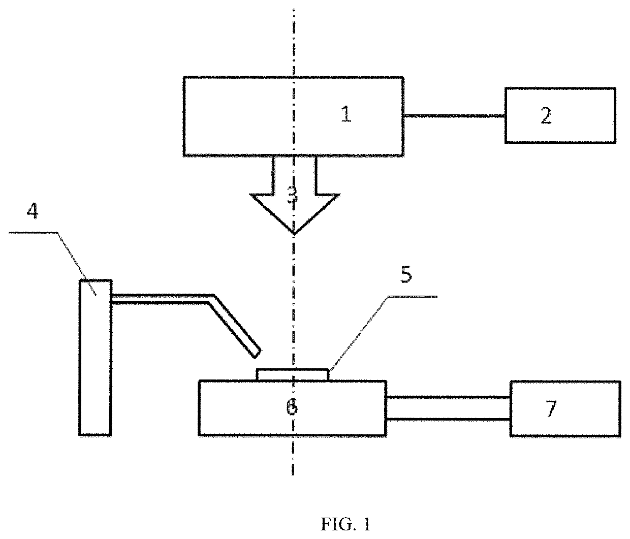

Image

  • Combined treatment method for improving corrosion resistance of metal component in chlorine-containing solution
  • Combined treatment method for improving corrosion resistance of metal component in chlorine-containing solution

Examples


embodiment 1

[0026]316L stainless steel was selected as an object under investigation and was prepared into 40 mm×40 mm×5 mm blocky samples. The sample to be treated was placed in an alcoholic solution, dust and oily stains on the surface were removed by an ultrasonic cleaner, and an essential crack detection process was accomplished, ensuring that no significant cracks and defects were present on the surface.

[0027]The 316L stainless steel sample was mounted on a loading platform 6 of the combined process unit, the center of a laser beam spot was registered with the upper left corner of a surface to be shocked of the matrix at a point A to serve as a starting position of shock peening, and the X-axis and Y-axis directions of a region to be shocked were coincident with the X-axis and Y-axis directions of the loading platform.

[0028]A 3.5% NaCl solution was sprayed onto the matrix surface of the 316L stainless steel sample by a spraying device 4 so as to form a liquid constraining layer having a th...

embodiment 2

[0033]AISI 304 stainless steel was selected as an object under investigation and was prepared into 40 mm×40 mm×5 mm blocky samples. The sample to be treated was placed in an alcoholic solution, dust and oily stains on the surface were removed by an ultrasonic cleaner, and an essential crack detection process was accomplished, ensuring that no significant cracks and defects were present on the surface.

[0034]The AISI 304 stainless steel sample was mounted on a loading platform 6 of the combined process unit, the center of a laser beam spot was registered with the upper left corner of a surface to be shocked of the matrix at a point A to serve as a starting position of shock peening, and the X-axis and Y-axis directions of a region to be shocked were coincident with the X-axis and Y-axis directions of the loading platform.

[0035]A 3.5% NaCl solution was sprayed onto the matrix surface of the 316L stainless steel sample by a spraying device 4 so as to form a liquid constraining layer hav...

embodiment 3

[0040]AM50 magnesium alloy was selected as an object under investigation and was prepared into 40 mm×40 mm×5 mm blocky samples. The sample to be treated was placed in an alcoholic solution, dust and oily stains on the surface were removed by an ultrasonic cleaner, and an essential crack detection process was accomplished, ensuring that no significant cracks and defects were present on the surface.

[0041]The AM50 magnesium alloy sample was mounted on a loading platform 6 of the combined process unit, the center of a laser beam spot was registered with the upper left corner of a surface to be shocked of the matrix at a point A to serve as a starting position of shock peening, and the X-axis and Y-axis directions of a region to be shocked were coincident with the X-axis and Y-axis directions of the loading platform.

[0042]A 3.5% NaCl solution was sprayed onto the matrix surface of the AM50 magnesium alloy sample by a spraying device 4 so as to form a liquid constraining layer having a th...


PUM

PropertyMeasurementUnit
Lengthaaaaaaaaaa
Fractionaaaaaaaaaa
Fractionaaaaaaaaaa

Abstract

Disclosed is a combined treatment method for improving corrosion resistance of metal component in chlorine-containing solution. First, the metal component is placed in the chlorine-containing solution. Large-area overlapping laser shock peening without an absorbing layer is used, when laser pulses are irradiated on the target metal component, the metal matrix surface absorbs the laser energy, vaporizes and expands to form a high-temperature and high-pressure plasma, a chlorine-containing passivation film is formed, to improve the surface corrosion resistance of the metal component. After that, the surface layer of the metal component is subjected to surface polishing, followed by large-area overlapping laser shock peening with an absorbing layer at room temperature, to further improve the corrosion resistance of the metal component. The combined treatment method of the present invention can be applied to improve the corrosion resistance of metal components in highly corrosive chlorine-containing environments of seawater and the like.

Description

BACKGROUND OF THE INVENTION1. Field of the Invention[0001]The present invention relates to the field of special processing and materials science, and more particularly to improvement of corrosion resistance of a metal component by firstly performing large-area overlapping laser shock peening without an absorbing layer on the metal component using a chlorine-containing solution as constraining layer, polishing the surface, and then treating the surface of the metal component by means of large-area overlapping laser shock peening with an absorbing layer at room temperature.2. Description of Related Art[0002]Offshore Engineering is very extensive in the content and the scope. In a broad sense, offshore engineering equipment includes ocean fishery equipment, offshore oil and gas development equipment, offshore transportation equipment, offshore tourism equipment, offshore power equipment, and offshore construction equipment. And in the narrow sense, it mainly refers to offshore oil and ...

Claims


Application Information

Patent Timeline
IPC IPC(8): C23C22/76C21D10/00C23C22/83C23C22/78
CPCC23C22/76C23C22/78C23C22/83C21D10/005C23C22/73
Inventor XUE, YAOLUO, KAIYULU, HAIFEILU, JINZHONG
Owner INST OF LASER & OPTOELECTRONICS INTELLIGENT MFG WENZHOU UNIV
Learn More