Lifetime estimation device, lifetime estimation method, and abnormality detection method of secondary battery
a lifetime estimation and secondary battery technology, applied in measurement devices, electrical testing, instruments, etc., can solve problems such as difficult to predict soh or soc, and achieve the effect of rapid deterioration of secondary batteries
- Summary
- Abstract
- Description
- Claims
- Application Information
AI Technical Summary
Benefits of technology
Problems solved by technology
Method used
Image
Examples
embodiment 1
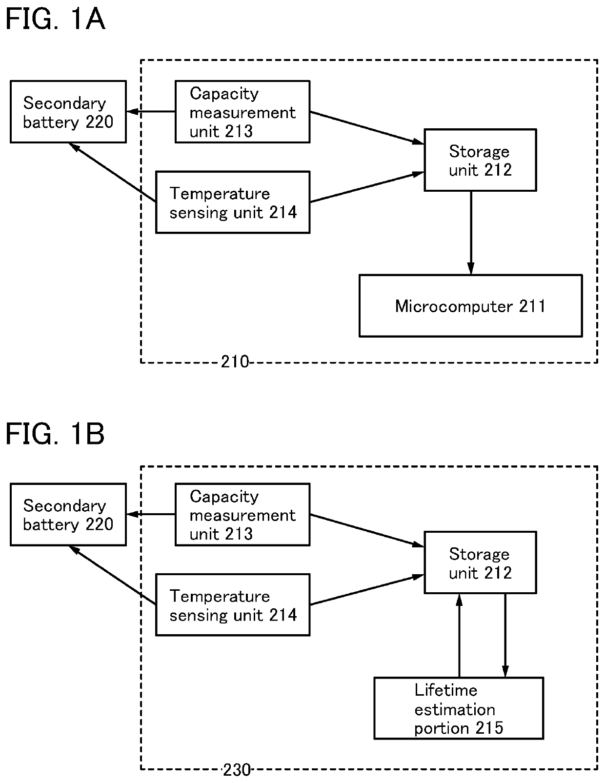
[0049]FIG. 1(A) is an example of a block diagram illustrating a hardware configuration example of a lifetime estimation device constructing a lifetime estimation system of a secondary battery. The lifetime estimation system of the secondary battery includes at least the secondary battery, a charge and discharge circuit, and a lifetime estimation device 210.
[0050]A hardware configuration of the lifetime estimation device 210 includes at least a CPU. Various known memories can be used as a storage unit 212, and the storage unit 212 refers to a database when storing a large amount of data.
[0051]A microcomputer 211 shown in FIG. 1(A) can also be called a microprocessor. In FIG. 1(A), the storage unit 212 and the microcomputer 211 are shown separately, but the microcomputer 211 also serves as part of the storage unit in some cases because the microcomputer 211 includes the CPU and the CPU may include a register, a memory, a cache memory, and the like.
[0052]With a communication portion, p...
embodiment 2
[0066]FIG. 1(B) is a block diagram illustrating a hardware configuration example of a lifetime estimation device 230 constructing a lifetime estimation system with the use of a neural network. Note that an example in this embodiment is partly different from that in Embodiment 1, and the same reference numerals are used for the same parts.
[0067]A hardware configuration of the lifetime estimation device 230 includes at least a CPU. Various known memories can be used as the storage unit 212, and the storage unit 212 refers to a database when storing a large amount of data.
[0068]With a communication portion, part of the storage unit is connected through a network.
[0069]Some devices (an electronic device, a vehicle, and the like) may include the plurality of secondary batteries 220. In that case, the secondary battery 220 illustrated in the drawing indicates a secondary battery which is to estimate the lifetime among the plurality of secondary batteries 220 provided in the device.
[0070]T...
embodiment 3
[0090]In this embodiment, an example of an IC chip used for the microcomputer 211 described in Embodiment 1 or the lifetime estimation portion 215 described in Embodiment 2 will be described.
[0091]FIG. 5 is a flow chart showing an example of a method for fabricating an electronic component. The electronic component is also referred to as a semiconductor package or an IC package. The electronic component has a plurality of standards and names corresponding to a terminal extraction direction and a terminal shape. Thus, an example of the electronic component is described in this embodiment.
[0092]A semiconductor device including a transistor is completed by integrating a plurality of detachable components on a printed board through an assembly process (post-process). The post-process can be completed through steps shown in FIG. 5. Specifically, after an element substrate obtained in the pre-process is completed (Step ST71), a back surface of the substrate is ground. The element substrat...
PUM
 Abstract
Description
Claims
Application Information
 - R&D
- Intellectual Property
- Life Sciences
- Materials
- Tech Scout
- Unparalleled Data Quality
- Higher Quality Content
- 60% Fewer Hallucinations
Browse by: Latest US Patents, China's latest patents, Technical Efficacy Thesaurus, Application Domain, Technology Topic, Popular Technical Reports.
© 2025 PatSnap. All rights reserved.Legal|Privacy policy|Modern Slavery Act Transparency Statement|Sitemap|About US| Contact US: help@patsnap.com


