Protective shield, shield wall and shield wall assembly

a shield wall and shielding technology, applied in the field of protective shields, can solve the problems of reduced compliance, users may not be comfortable wearing vests or similar protection in particular social situations, users will forgo protection for comfort, etc., to achieve the effect of improving the ballistic performance of composites, increasing the ballistic performance of shields and shield walls, and high strength

Active Publication Date: 2021-07-15
GRAPHENE COMPOSITES LTD
View PDF6 Cites 1 Cited by
  • Summary
  • Abstract
  • Description
  • Claims
  • Application Information

AI Technical Summary

Benefits of technology

[0064]In an embodiment, each first layer is bonded to an adjacent second layer. In other words, each graphene layer is bonded to an adjacent aerogel layer. This can be directly (i.e. with direct contact between the graphene layer and the aerogel layer and bonded provided by the adhesive nature of either of the first or second layer) or indirectly (with another component, for example an adhesive or another layer, provided between the graphene layer and the adjacent aerogel layer). This is advantageous as this has been found to improve ballistic performance of the composite and thus will increase the ballistic performance of the shields and shield walls of the above aspects. By adjacent second layer, it is meant one of the second layers on either side of the first layer (i.e. next to the first layer). In some embodiments, the structure is orientated with an upper graphene layer being bonded to a lower aerogel layer. This can, for example, then be arranged with the graphene layer being the layer closest (of the two layers) to or defining the strike face and the aerogel layer behind the graphene layer, relative to the front strike face of the shield or shield member.
[0065]In some embodiments, each first layer is directly bonded to an adjacent second layer such that the graphene layer is provided on an adjacent aerogel layer. In some embodiments, all of the layers of the composite are bonded together. In other words, (all of) the first and second layers are bonded together, as well as any other layers present in the composite. Thus, a first layer may be bonded to the two adjacent second layers, and vice versa. When bonded together in a multi-layered sandwich, the resulting composite has both high strength and extreme lightness, as a result of the high aggregate strength. As such, the shields and shield walls will be particularly effective at preventing damage, while also remaining light. Accordingly, in some embodiments there is a composite formed of alternating layers of graphene and nano-porous materials (aerogels), wherein bonding is provided between the graphene and aerogel layers
[0066]In another embodiment of any of the above aspects, a fastening element or means is provided to secure the first and second layers of the composite structure together, the fastening element or means being provided along an edge of the composite structure. By ‘provided along the edge’ it is meant that the fastening element or means (e.g. stitching or staples) are provides adjacent and along the edges of the composite structure (from a top-down view) and extend through the layers to secure the layers together. The fastening element constrains the edges of the composite. It has been found that this can dramatically improve the performance of composite and the same level of penetration-resistance (e.g. stab) and / or ballistic performance can be achieved with fewer layers. In another embodiment, a fastening element or means is provided to secure the layers of the composite structure together, the fastening element or means being provided along an edge of the composite structure. In embodiments where the composite structure defines the body or extends over the majority of the body, the fastening element or means can be provided around the edge of the strike face.
[0067]In an embodiment, the composite structure comprises between 2 and 250 first layers (i.e. layers comprising graphene) and / or 2 and 250 second layers (i.e. layers comprising aerogel). In an embodiment, the composite comprises at least 5 layers, at least 10 layers or, in some embodiments, at least 25 layers. For example, there may be 10 to 200 layers, 25 to 150 layers, 50 to 125 layers. The number of first layers may be the same as the number of second layers. In some embodiments, the number of first layers is at least 5, at least 10 or, in some embodiments, at least 25. For example, there may be 10 to 100 layers or 25 to 50 first layers. It has been found that an increased number of layers can lead to a projectile being stopped earlier in the composite than in cases where there are fewer layers. This may be as a result of a shear thickening effect.
[0068]In an embodiment, at least one of the second layers is a polyimide aerogel. In a further embodiment, each (all) of the second layers is a polyimide aerogel. Polyimide aerogels have been found to be particularly effective in such a composite structure as they have some flexibility while also having a relatively high-tensile strength compared to other aerogels. This can also impart flexibility to the whole shield / shield wall, which is particularly advantageous as it makes it easier to store and the shield can more readily conform to the object(s) or person(s) it is being used to protect. Furthermore, polyimide-based aerogels also form less dust than silicon-based aerogels, reducing the likelihood of inhaling any aerogel-derived dust. Polyimide-based aerogels also recover from impacts / compressions better than silicon-based aerogels—a key performance criteria for impact protection and providing improved multi-hit protection.
[0069]In another embodiment of any of the above aspects, the composite structure further comprises a third layer comprising a polymer, the third layer being provided adjacent a second layer comprising an aerogel. The polymer may also provide resilience for the aerogel layer and it has been found that polymer layers used in conjunction with aerogel layers improves the effectiveness of the composite structure by helping to hold the structure together and dispersing forces acting upon the structure. This is particularly effective for the polymer layers located in front of the aerogel layer (relative to the direction of a force acting upon the structure—for example, with the composite arranged so that the polymer is located between the strike face and the aerogel (or with the polymer defining the strike face). Thus, in some embodiments, the first layer comprising the polymer is provided as an upper layer, with a second layer below or behind the layer. In some embodiments, there may be a plurality of different polymers and / or the polymer may be a copolymer. The polymer can result in the first layer acting as a binding layer adapted to hold together the structure of an adjacent aerogel layer. The polymer may be a single polymer or may be a polymer blend. The polymer can have a number average molecular weight of at least 1,000 Da; for example, at least 10,000 Da (e.g. 10,000 Da to 100,000 Da). In an embodiment, the polymer is selected from polyurethane, polyethylene (including ultra-high molecular weight polyethylene), polypropylene, polyester, polyamide, polyimide, epoxy resin or combinations thereof. In some embodiments, the polymer comprises polyurethane and / or an epoxy resin (e.g. a thermosetting network polymer formed from an epoxy resin with a hardener). Polyurethanes are particularly advantageous as the structure comprises rigid sections (based around the isocyanate groups) and soft flexible regions (around the diol groups), which make it suited to providing impact protection while remaining flexible. Other components can also be present. Use of a cross-linked polymer is particularly advantageous as this encourages dissipation of a force across the entire polymer layer.

Problems solved by technology

However, in order to protect a user, a user must be wearing or carrying these articles at all times, which can be onerous particularly where the article is bulky or uncomfortable (e.g. in the case of a vest) or heavy.
Thus, often users will forgo protection for comfort.
Users also may not be comfortable wearing a vest or similar protection in particular social situations, for example at work or at a social event and, therefore, compliance is reduced.
Moreover, while vests can be effective when an impact or projectile hits the chest or back of a user, they can leave the user exposed around other parts of the body, for example on the head or limbs.
This can be a particular risk when the source of the impact is near to the user or object; for example, where the force is from a handheld weapon, such as a knife or a blunt force, and / or where the source of the projectile (e.g. a bullet) is at close range.
Any protection that does cover these higher risk areas results in more inconvenience (e.g. in respect of mobility) and is not practical for day-to-day protection in lower risk situations.
Bullet-proof or stab-proof vests are also limited in that they are only designed to protect a single person and cannot easily be used to protect more than one individual.
Thus, during an event requiring the use of such a vest, there need to be sufficient vests for each individual, otherwise there will be insufficient protection.
Often, articles designed for penetration resistance (from edged weapons (e.g. bladed articles), for example) also include additional penetration resistant layers, such as a metal plate or chainmail, but these can be heavy, cumbersome and offer low protection against ballistics and, therefore, do not assist in encouraging a user to wear or otherwise use the articles.
Similarly, other non-wearable protective articles suffer from similar issues.
However, these barriers are difficult and / or slow to deploy, and their deployment may not even be possible for a human without assistance from mechanical devices such as electric motors.
Such barriers must deploy slowly as a quickly moving mass of steel can be fatal if it strikes a person from above.

Method used


Image

  • Protective shield, shield wall and shield wall assembly
  • Protective shield, shield wall and shield wall assembly
  • Protective shield, shield wall and shield wall assembly

Examples


example 1

[0129]A 125 μm flexible polyimide aerogel layer (AeroZero 125 micrometer polyimide aerogel film; BlueShift Inc (US)) was cut to size and coated with a 20 μm layer of a polyurethane (PX30; Xencast UK Flexible Series PU Resin system. Manufacturer reported properties: Hardness of 30-35 (Shore A); Tensile strength 0.7-1.2 MPa; Elongation 100-155% at break; Tear Strength 3.5-3.8 kN / m) using a slot die process. After coating, the polyurethane layer was left to cure at room temperature for 12 hours. The aerogel / polyurethane composite layer (backing structure) was then cut to size.

[0130]An ultra-high molecular weight polyethylene (UHMWPE) fabric (Spectra 1000; 200D; Honeywell; 80 gsm; Warp Yarn 24 Tex; Weft Yarn 25 Tex; Encs×Picks / 10 cm 177×177; Plain Weave) was cut to the same size as the backing structure and was applied to the upper surface of the backing structure (i.e. the exposed surface of the polyurethane layer).

[0131]The laminate structure was then further built up by adding additi...

example 2

[0133]A 125 μm flexible polyimide aerogel layer (AeroZero 125 micrometer polyimide aerogel film; BlueShift Inc (US)) was cut to size and coated with a 20 μm layer of graphene (Elicarb graphene powder; Thomas Swan & Co Ltd UK Product No. PR0953) in a polyurethane matrix (PX30; Xencast UK Flexible Series PU Resin system. Manufacturer reported properties: Hardness of 30-35 (Shore A); Tensile strength 0.7-1.2 MPa; Elongation 100-155% at break; Tear Strength 3.5-3.8 kN / m) using a slot die process. After coating, the graphene / polyurethane layer was left to cure and subsequently cut to size.

[0134]The graphene / polyurethane layer comprised 5 wt % functionalised graphene (Elicarb graphene powder; Thomas Swan & Co Ltd UK Product No. PR0953), which was dispersed in the polyurethane prior to slot die processing. More specifically, prior to dispersion, the graphene was treated with a plasma treatment of “oxygen” functionalisation using the Hydale HDLPAS process, which is set out in WO 2010 / 142953...

example 3

[0139]Using the techniques described in respect of Examples 1 and 2, above, a composite structure comprising 26 layers of UHMWPE fibre (DOYENTRONTEX Bulletproof unidirectional sheet; WB-674; 160 g / m2; 0.21 mm thickness) alternating with 25 layers of backing structure was prepared. The backing structure comprised 125 μm flexible polyimide aerogel (AeroZero 125 micrometer film from BlueShift Inc (US)) layered with a 20 μm layer of a polyurethane (PX60; Xencast UK) (i.e. 25 layers of aerogel alternating with 25 layers of polyurethane). In this Example, the polyurethane was infused with 0.2% graphene (Elicarb graphene powder; Thomas Swan & Co Ltd UK Product No. PR0953) using the technique set out in respect of Example 2. Thus, the composite had the following repeating pattern arrangement of layers “. . . UHMWPE layer / polyurethane+graphene layer / aerogel layer / UHMWPE layer / polyurethane+graphene layer / aerogel layer . . . ”.


PUM


Abstract

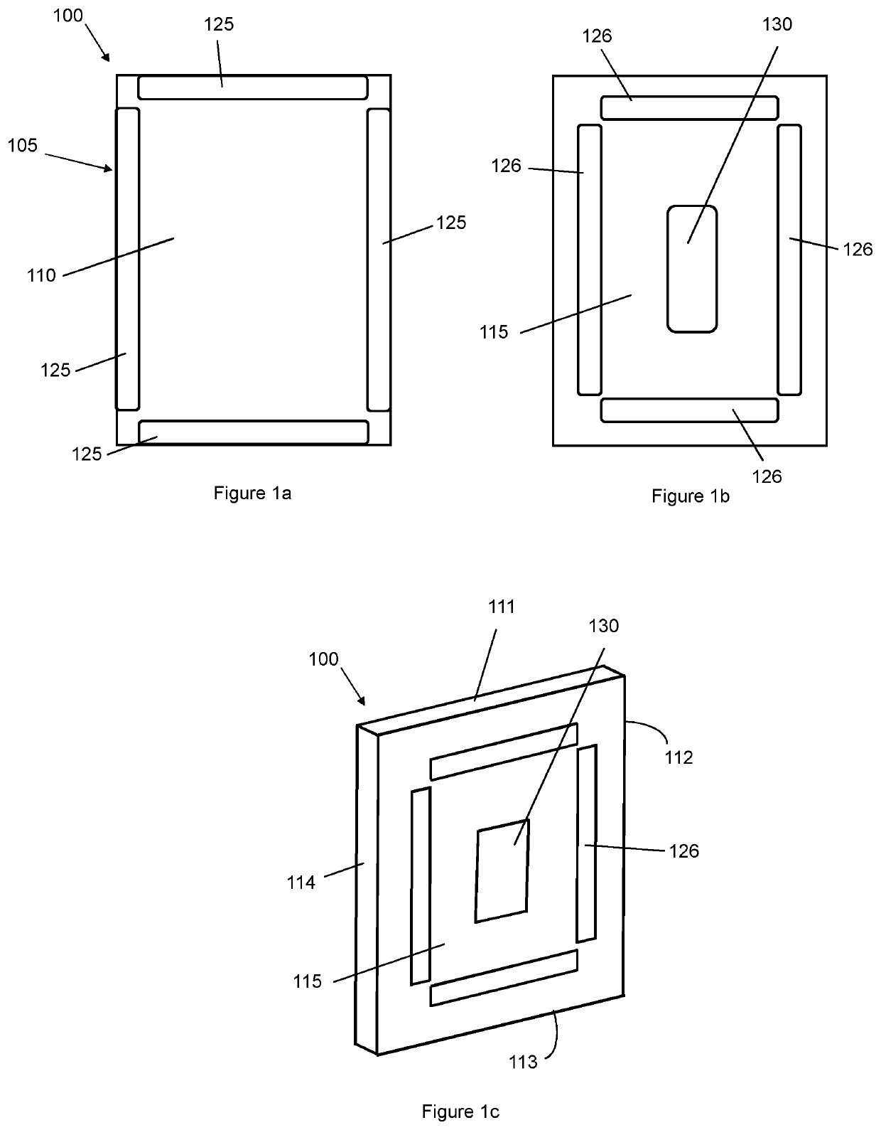
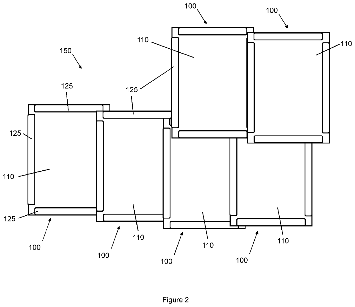
A protective shield (100) comprises a body (105) for protecting a user from a projectile or impact, the body comprising a front strike face (110) and an opposing rear face (115); and a connector arrangement (125, 126) provided on the body adapted so as to allow the shield to connect to an adjacent protective shield, wherein the strike face has a perimeter defined by the edges of the strike face; and wherein the connector arrangement is arranged so that an adjacent protective shield can be connected to the connector arrangement with the body of the adjacent protective shield abutting and/or overlapping with the strike face of the protective shield at any point about the perimeter of the strike face.

Description

FIELD OF THE INVENTION[0001]The present invention relates to a protective shield, a shield wall and a deployable shield wall assembly.BACKGROUND TO THE INVENTION[0002]Articles such as bullet-proof or stab-proof vests are designed to protect a wearer or an object surrounded by the articles from an impact (e.g. from a projectile or blunt force) or from penetration (e.g. from a sharp object or bullet). However, in order to protect a user, a user must be wearing or carrying these articles at all times, which can be onerous particularly where the article is bulky or uncomfortable (e.g. in the case of a vest) or heavy. Thus, often users will forgo protection for comfort. Users also may not be comfortable wearing a vest or similar protection in particular social situations, for example at work or at a social event and, therefore, compliance is reduced. Moreover, while vests can be effective when an impact or projectile hits the chest or back of a user, they can leave the user exposed aroun...

Claims


Application Information

Patent Timeline
Patent Type & Authority Applications(United States)
IPC IPC(8): F41H5/013F41H5/08F41H5/04
CPCF41H5/013F41H5/0492F41H5/08F41H5/06
Inventor CHEN, SANDY WINTHROP
Owner GRAPHENE COMPOSITES LTD
Why Eureka
Try Eureka