An electrolytic composition and cathode for the nitrogen reduction reaction

a technology of electrolytic composition and nitrogen reduction reaction, which is applied in the direction of physical/chemical process catalysts, cell components, bulk chemical production, etc., can solve the problems of high faradaic efficiency, low nh/sub>yield rate, and low faradaic efficiency of many reported electrocatalysts, and achieve superior n2 selectivity and reduce dinitrogen

Pending Publication Date: 2021-08-05
MONASH UNIV
View PDF0 Cites 2 Cited by
  • Summary
  • Abstract
  • Description
  • Claims
  • Application Information

AI Technical Summary

Benefits of technology

The patent describes a method for producing ammonia using a power supply and an electrocatalytic composition. The ammonia can be used as a fertilizer or can be further converted to ammonium ions for other applications. The method can be performed using a solar or wind-generated power source and can be controlled to produce ammonia at the point of need. The ammonia can be produced using a photovoltaic solar cell or a direct current power source. The invention also provides methods for reducing dinitrogen to ammonia using the electrocatalytic composition and a source of hydrogen. The ammonia can be recovered in gaseous or ammonium ion form depending on the nature of the electrolyte.

Problems solved by technology

Providing food and energy sufficient to meet the requirements of a burgeoning world population remains an ongoing challenge for humanity.
Consequently, the process consumes approximately 2% of global energy supply and contributes ˜1.5% of global greenhouse gas emissions.
Unfortunately, the 6e− and 6H+ NRR is kinetically sluggish and thus electrochemically disadvantaged over the more facile 2e− and 2H+ hydrogen evolution reaction (HER) shown in equation (2).
As a result of competition from the HER, many reported electrocatalysts suffer both from very low faradaic efficiency and / or low NH3 yield rates when evaluated in aqueous electrolytes.
Moreover, some reports of high faradaic efficiencies are regarded with scepticism by those skilled in the art (absent evidence of high ammonia yield rates over extended periods of time) due to residual nitrogen contaminants in the catalysts, particularly when ammonium salt precursors were used (see e.g. Ozin, “Nitrogen Reduction Reactions: Fact or Artifact”, Advanced Science News 2018, March 2018).

Method used


Image

  • An electrolytic composition and cathode for the nitrogen reduction reaction
  • An electrolytic composition and cathode for the nitrogen reduction reaction
  • An electrolytic composition and cathode for the nitrogen reduction reaction

Examples


example 1

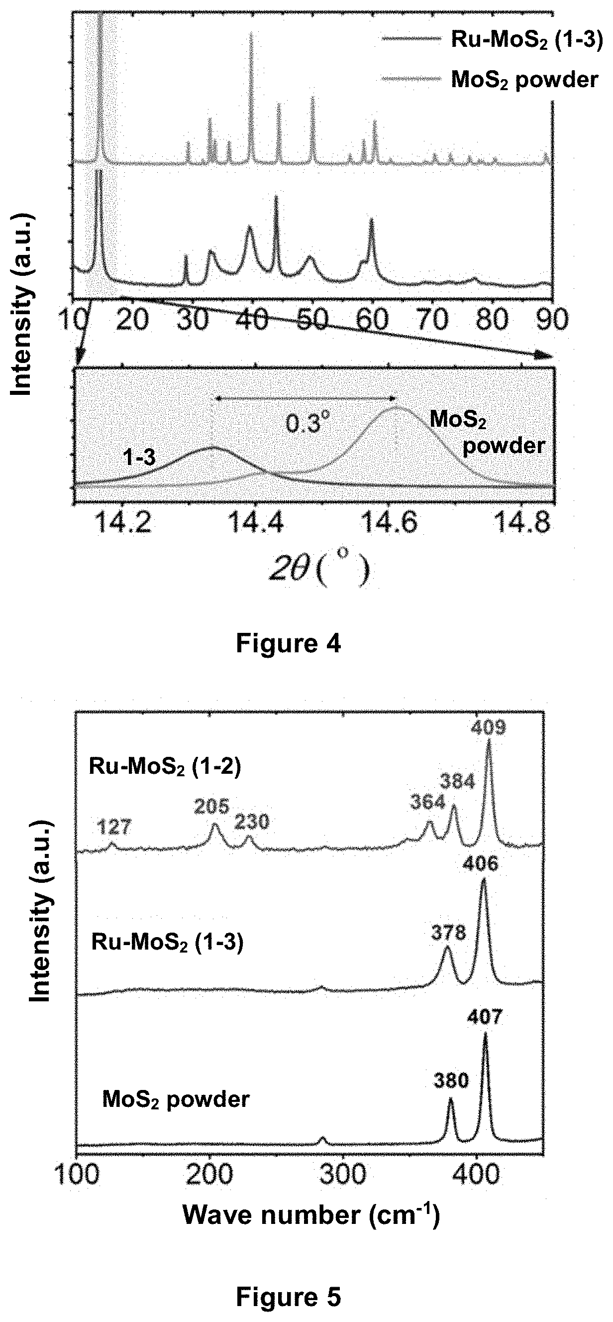
[0166]MoS2 powder (1 g) was lithiated in 10 ml n-butyllithium for 72 hours under argon gas to produce Li—MoS2 (sample 1-1, see Table 2). This process is known to produce Li—MoS2 with the MoS2 layers in the 1T polymorphic phase (Wang et al, Nanoscale 2015, 7, 19764-19788). When Li—MoS2 is exposed to hydrolytic conditions, the lithium metal is known to exfoliate the MoS2 host. The exfoliated 1T polymorphic form thus formed is believed to be stable against reversion to 2H for the duration of short electrochemical experiments. Thus, when a suspension of sample 1-1 was dropcast onto a cathode and electrochemically evaluated in aqueous electrolytes (see examples 5 and 6), the resulting MoS2 material (designated sample 1-4 in Table 2) was believed to be exfoliated MoS2 at least partially in the 1T polymorphic form.

[0167]RuCl3 (60 mg) and Li—MoS2 (100 mg) were dispersed in 10 ml of anhydrous N-methylpyrollidone (NMP), and the mixture was transferred to a teflon-lined 20 mL autoclave. The au...

example 2

[0179]A mixture of sodium oleate, RuCl3 (1 mM) and FeCl3 (1 mM) in water was prepared. The Ru—Fe-oleate mixture was transferred to hexane, and then drop-cast onto carbon fibre paper (CFP). After removing the solvent by evaporation overnight, the Ru—Fe-oleate / CFP was placed in a tube furnace and calcined at 500° C. in Ar for 3 h. During the calcination, the Fe oxidised to form Fe2O3 initially, and the Ru was later reduced in situ when the oleate decomposed at high temperatures. The resultant Ru—Fe2O3 material, designated sample 2-1, was obtained and used as electrode for a nitrogen reduction reaction experiment, without adding a binder.

[0180]Control electrodes comprising only one of Ru nanoparticles or Fe2O3 were prepared by a similar methodology, with the intention of demonstrating the importance of the synergistic effect between catalytically active sites and semiconducting substrate. Thus an electrode of Ru nanoparticles on CFP, designated sample 2-2, was prepared using only RuCl3...

example 3

[0181]RuCl3 (10 mg) was dissolved in 20 mL DI water in the presence of TiO2 nanoparticles (100 mg). After sonicating and stirring for 30 min, 35% hydrazine solution (10 mL) was added dropwise. The mixture was stirred for another 2h before filtering the solids, washing with copious water and then drying at 60° C. under vacuum overnight to produce an Ru—TiO2 catalyst designated sample 3-1. It is expected that the Ru is present as metallic clusters in sample 3-1, and that the TiO2 is present exclusively in the rutile polymorphic phase.


PUM

PropertyMeasurementUnit
Percent by massaaaaaaaaaa
Sizeaaaaaaaaaa
Electric potential / voltageaaaaaaaaaa

Abstract

The invention provides a cathode for the nitrogen reduction reaction, comprising an electrically conductive substrate and an electrocatalytic composition on the substrate, wherein the electrocatalytic composition comprises: a support material present in one or more crystalline phases; and metallic clusters dispersed on the support material, the metallic clusters comprising at least one metal selected from ruthenium, iron, rhodium, iridium and molybdenum, wherein at least 80 mass % of the support material is present in a semiconductive crystalline phase having a conduction band minimum energy below (more positive than) −0.3 V relative to the normal hydrogen electrode (NHE).

Description

TECHNICAL FIELD[0001]The invention relates to electrocatalytic compositions for the nitrogen reduction reaction and to methods of producing such electrocatalytic compositions. The invention also relates to cathodes for the nitrogen reduction reaction comprising an electrocatalytic composition, and an electrochemical cell for reduction of dinitrogen to ammonia, which includes such a cathode. The invention further relates to methods of reducing dinitrogen to ammonia on an electrocatalytic composition. The electrocatalytic compositions generally comprise a support material predominantly present in a semiconductive crystalline phase with a low conduction band minimum energy, and a metallic composition comprising at least one metal selected from ruthenium, iron, rhodium, iridium and molybdenum dispersed on the support material.BACKGROUND OF INVENTION[0002]Providing food and energy sufficient to meet the requirements of a burgeoning world population remains an ongoing challenge for humani...

Claims


Application Information

Patent Timeline
IPC IPC(8): C25B11/054C25B1/27C25B11/057C25B11/081
CPCC25B11/054C25B11/081C25B11/057C25B1/27C01C1/0411H01M4/86H01M4/9041H01M4/9075B01J23/462B01J23/464B01J23/468B01J23/28B01J23/745H01M2004/8689C01C1/04C25B1/00Y02P20/52Y02E60/50C25B11/097C25B11/067C25B15/08
Inventor MACFARLANE, DOUGLAS R.SURYANTO, BRYAN HARRY RAHMATWANG, DABINDU, HOANG-LONG
Owner MONASH UNIV
Why Eureka
Try Eureka