
Fine particle sensor with cascaded microscales

a microscale sensor and fine particle technology, applied in the direction of instruments, material analysis, withdrawing sample devices, etc., can solve the problems of difficult application, difficult to define a stable correction factor, and difficult to implement the filter sampling followed by weighing under standard conditions

Pending Publication Date: 2021-08-19
CENT SCI & TECHN DU BATIMET +2
View PDF1 Cites 0 Cited by
  • Summary
  • Abstract
  • Description
  • Claims
  • Application Information

AI Technical Summary

Benefits of technology

The patent describes a resonator device that can detect small amounts of mass using a high-quality factor resonant element. The device has a reduced size and cost, making it commercially viable for large-scale deployment and adaptable to specific environments and public needs. The device's membrane surface is made of black silicon with nanopillars that reduce particle rebound effects, providing a confined deposition pattern. The device also has an air impactor body with open / close mechanisms to control the flow rate of the aerosol flow. The original feature of the device is the co-integration of a sorting system, microbalances, and reference / calibration functions, allowing for continuous and real-time monitoring of air quality.

Problems solved by technology

This method of filter sampling followed by weighing under standard conditions is very cumbersome to implement and identified as “difficult to apply in the context of routine data production of measurement networks” by AIRPARIF in a summary report dated 2008 (AIRPARIF, 2008).
This method, which has the advantage of being miniaturizable and inexpensive, does not make it possible to define a stable correction factor with reference measurements, which makes it unsuitable according to the standards defined by the European standard.
It should be noted, however, that these devices are currently used very little as they have many metrological limitations (Berthelot, 2015).
From the previous elements it becomes very clear that there are currently no devices for real-time or low time step measurements, particulate mass concentrations meeting European requirements and of dimensions and operation suitable for multiple deployment in indoor or outdoor environments.

Method used


Image

  • Fine particle sensor with cascaded microscales
  • Fine particle sensor with cascaded microscales
  • Fine particle sensor with cascaded microscales

Examples


Embodiment Construction

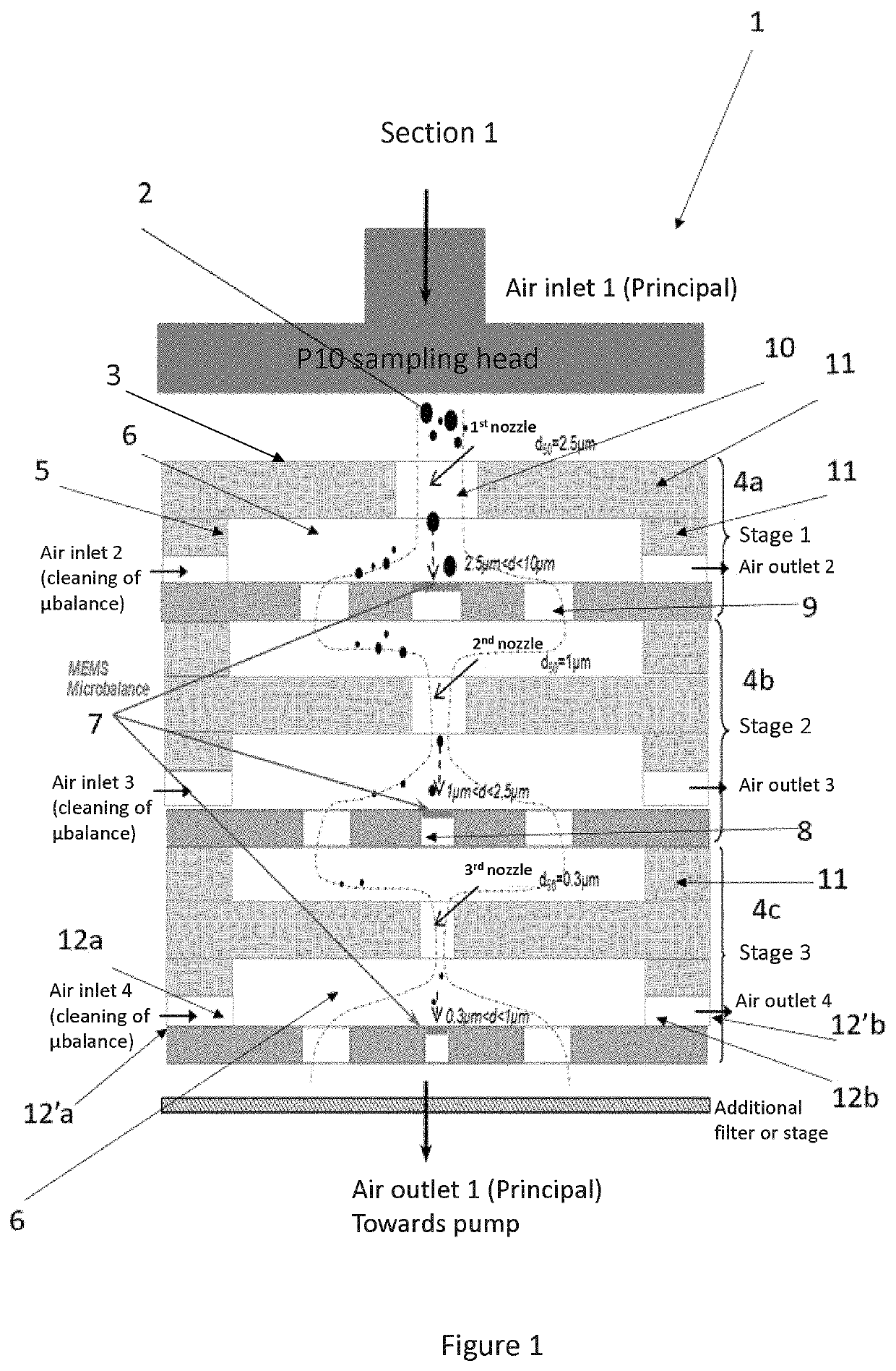
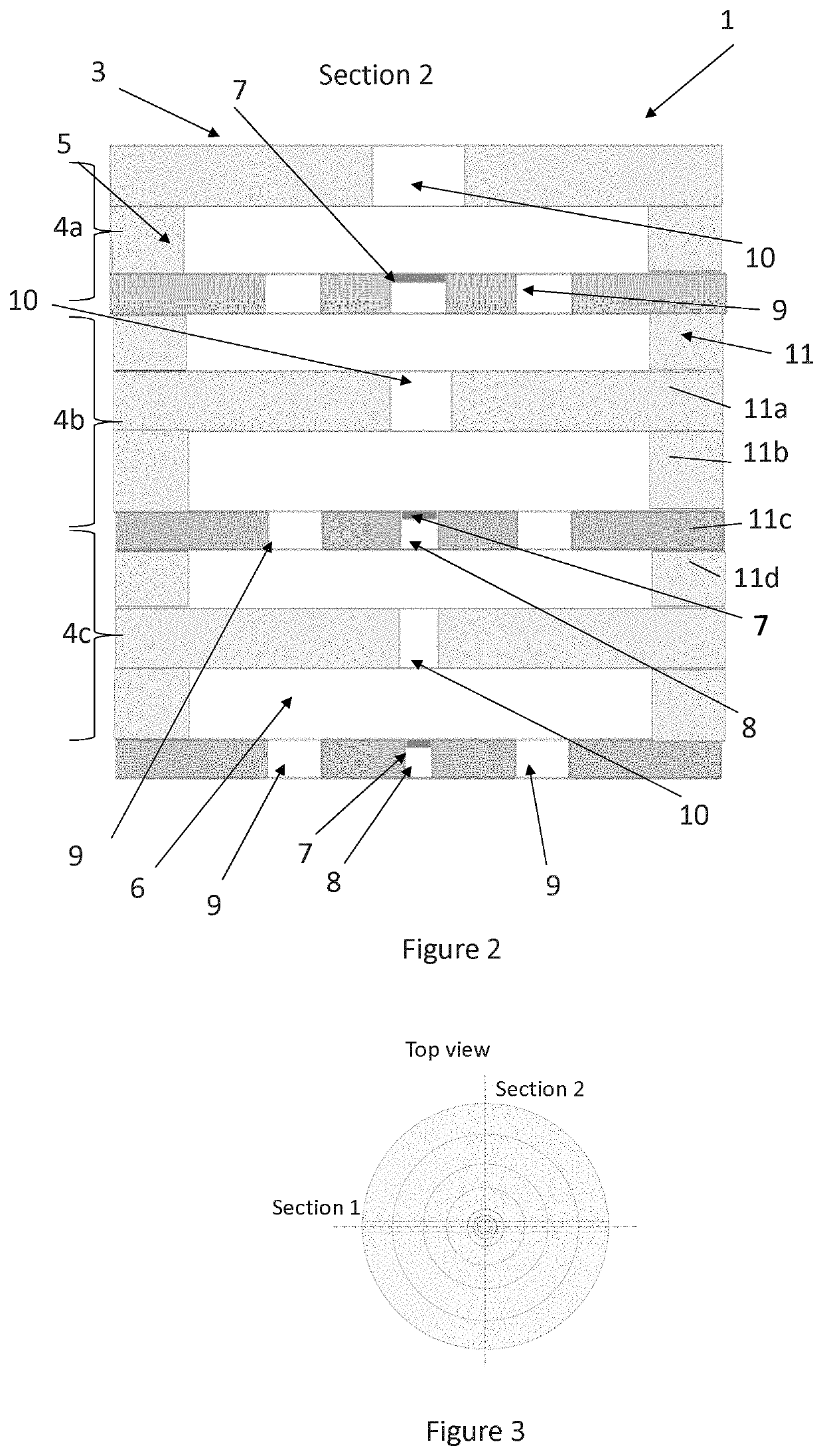
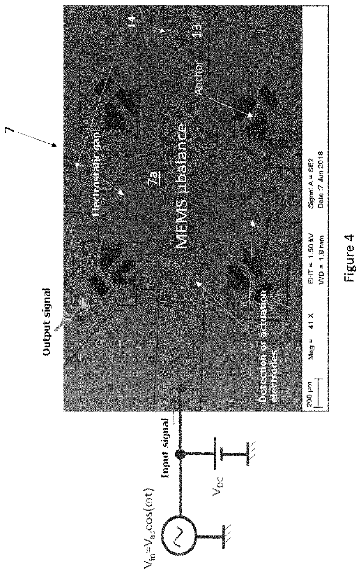
[0081]The present invention presents a sensor 1 for the continuous in-situ analysis of an aerosol flow, allowing the measurement of the mass of micron / submicron particles 2 suspended in the air flow and represented in FIGS. 1 to 3.

[0082]This sensor 1 includes a device of aeraulic sorting allowing to perform the granulometry of the particles 2 according to their size while integrating the measurement systems.

The device of aeraulic sorting according to the present invention:[0083]an impactor body 3 with cascade of one or more stages 4a, 4b, 4c, presenting at the entry a sampling head of the particles (the size, more particularly the aerodynamic diameter which corresponds to the average diameter, of these particles being advantageously lower than 10 micrometers, that is to say particles called in the state of the art PM10), followed by a flow pipe 6 formed for each stage and following the direction of the aerosol flow: at least one axial nozzle 10, followed by lateral openings 9 at the...


PUM


Abstract

A sensor for the continuous in-situ analysis of an aerosol flow for measuring the mass of the micron / submicron particles suspended in the air flow, including an aeraulic sorter allowing the particles to be sorted according to their size with an impactor body with a cascade of one or more stages; at least one MEMS microbalance per stage, with an oscillating silicon membrane located on the impaction zone of the particles; processor connected to each MEMS microbalance to determine the mass of all the particles on the impaction zone; a system for cleaning the MEMS microbalances allowing the evacuation of the particles from the MEMS microbalances; means for driving the aerosol flow.

Description

FIELD OF THE INVENTION[0001]The present invention relates to a sensor for measuring the mass concentration of fine particles for air pollution, potentially indoor air and contamination with a biological origin.BACKGROUND OF THE INVENTION[0002]Particulate pollution is implicated in the occurrence of various cardiovascular, cerebrovascular and respiratory pathologies through mechanisms of toxicity described by the “Haut Conseil de la Santé Publique” (HCSP) (“Pollution par les particules 2 dans l'air ambiant—Recommandations pour protéger la santé”, 2012). Atmospheric pollution and particles in the air have been classified as “definitely carcinogenic to humans” in 2013 by the International Agency for Research on Cancer (IARC) (“Monographs on the evaluation of carcinogenic risks to humans”; volume 109). This pollution has also been identified as being responsible for premature deaths, of the order of 42,000 per year in France, which compliance with the thresholds recommended by the WHO (...

Claims


Application Information

Patent Timeline
IPC IPC(8): G01N15/02G01G3/16G01N1/22G01N5/00
CPCG01N15/0255G01G3/16G01N2015/0261G01N5/00G01N1/2208
Inventor ALGRE, EMMANUELLESOYSAL, UGURMARTY, FREDERICMOTZKUS, CHARLESROBINE, ENRICBERTHELOT, BRICEGEHIN, EVELYNE
Owner CENT SCI & TECHN DU BATIMET
Learn More