CORROSION RESISTANT CuZn ALLOY
- Summary
- Abstract
- Description
- Claims
- Application Information
AI Technical Summary
Benefits of technology
Problems solved by technology
Method used
Image
Examples
production example 1
[Production Example 1] (Example)
[0088]A CuZn alloy was produced as follows.
[0089]The following Cu raw materials and Zn raw materials were prepared as raw materials:
[0090]Cu raw material: high purity metallic copper (6N) (purity 99.9999%); and
[0091]Zn raw material: high purity metal zinc (4N5) (purity 99.995%).
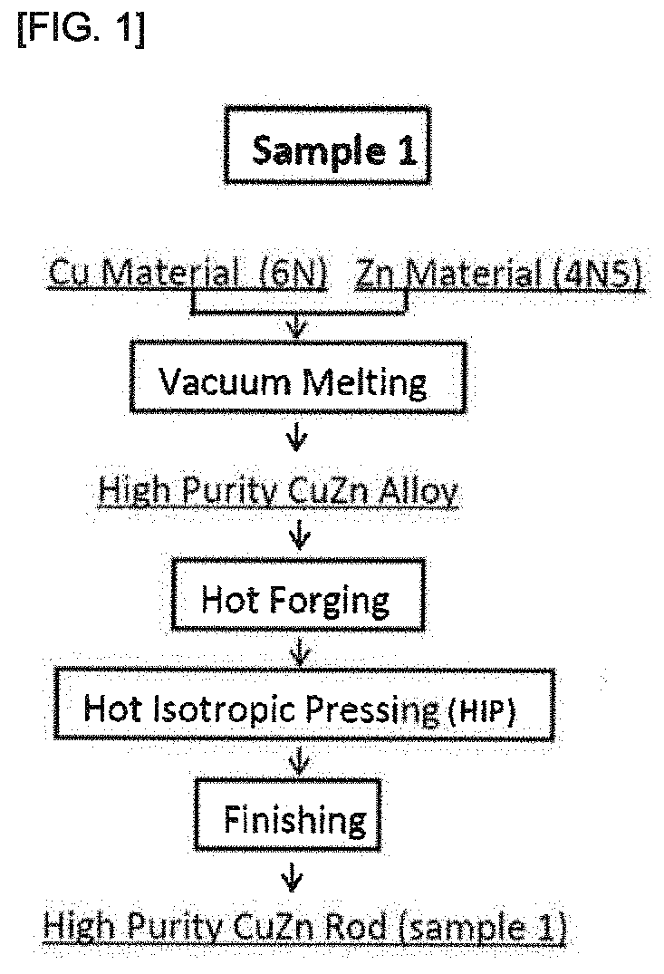
28.35 kg of the raw material Cu and 17.15 kg of the raw material Zn were subjected to vacuum melting (conditions: vacuum-drawn to 10−1 Pa and then set to 400 torr atmosphere and maintained at 1050° C. for 30 minutes) to obtain a high purity CuZn alloy. An ingot pipping portion at an upper portion of the ingot was removed from the resulting CuZn alloy, and forging was carried out for the ingot having φ 132, a length of 275 mm, and a weight of 31.5 kg.
[0092]Forging was carried out by preheating the ingot at a temperature of 850° C. for 3 hours, and carrying out reheating in four steps of: firstly from φ 135 to φ 130 and then φ 130→80 mm square→50 mm square→φ41 mm at 850° C. for 1...
production example 2
[Production Example 2] (Comparative Example)
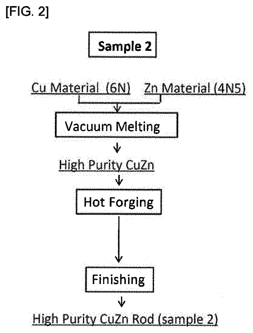
[0097]In the same procedure as that of Production Example 1, a Cu raw material and a Zn raw material were prepared and subjected to vacuum melting to obtain a high purity CuZn alloy, which was subjected to hot forging. The high purity CuZn alloy subjected to the hot forging were subjected to finishing under the same conditions as those of Production Example 1, without carrying out hot isotropic pressing (HIP processing), to obtain high purity CuZn rods (high purity products) (sample 2). An explanatory view of the procedure of Production Example 2 is shown in FIG. 2.
production example 3
[Production Example 3] (Comparative Example)
[0098]A CuZn alloy was produced as follows.
[0099]The following Cu raw materials and Zn raw materials were prepared as raw materials:
[0100]Cu raw material: metallic copper ingot (4N) (purity 99.99%); and
[0101]Zn raw material: metallic zinc ingot (3N) (purity 99.9%).
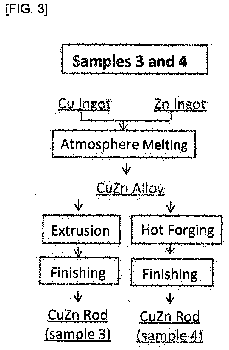
[0102]28.35 kg of the raw material Cu and 17.15 kg of the raw material Zn were melted in the atmosphere (conditions: maintained at 1050° C. for 30 minutes) to obtain a CuZn alloy.
[0103]An ingot pipping portion at an upper portion of the ingot was removed from the resulting CuZn alloy, and the ingot having Ψ 132, a length of 248 mm and a weight of 28.4 kg was extruded.
[0104]The extrusion was carried out using a die having φ 40 such that a finished diameter would be about φ 41, while heating the ingot at 700° C. An extrusion pressure at this time was from 150 to 170 kg / cm2. The extruded ingot was cut on the extruder outlet side every 650 mm to obtain four alloy rods (sample 3).
PUM
| Property | Measurement | Unit |
|---|---|---|
| Fraction | aaaaa | aaaaa |
| Fraction | aaaaa | aaaaa |
| Fraction | aaaaa | aaaaa |
Abstract
Description
Claims
Application Information
 - R&D
- Intellectual Property
- Life Sciences
- Materials
- Tech Scout
- Unparalleled Data Quality
- Higher Quality Content
- 60% Fewer Hallucinations
Browse by: Latest US Patents, China's latest patents, Technical Efficacy Thesaurus, Application Domain, Technology Topic, Popular Technical Reports.
© 2025 PatSnap. All rights reserved.Legal|Privacy policy|Modern Slavery Act Transparency Statement|Sitemap|About US| Contact US: help@patsnap.com


