
Optical fiber

a technology of optical fibers and fibers, applied in the field of optical fibers, can solve the problems of increasing the lateral pressure applied to the optical fibers, causing the loss of transmission loss (microbending loss) induced by minute bending by lateral pressure, and achieves excellent lateral pressure characteristics, no increase in transmission loss, and excellent uniformity.

Pending Publication Date: 2022-01-13
SUMITOMO ELECTRIC IND LTD
View PDF7 Cites 0 Cited by
  • Summary
  • Abstract
  • Description
  • Claims
  • Application Information

AI Technical Summary

Benefits of technology

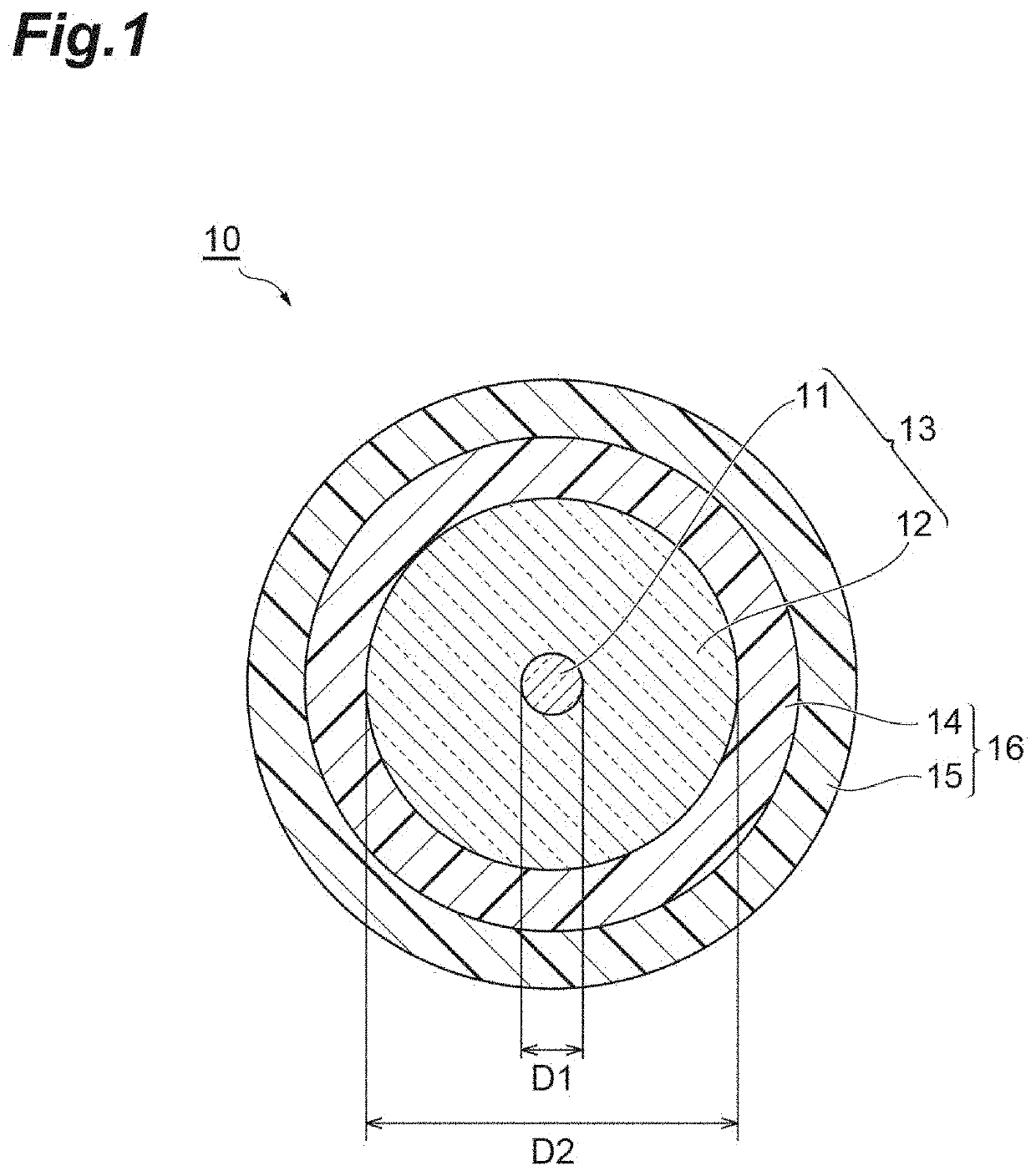
The present patent is about an optical fiber that has a coating resin layer with a primary layer in contact with the glass fiber and a secondary layer coating the outer periphery of the primary layer. The primary layer has a low modulus and a specific outer diameter, while the secondary layer has a specific glass transition temperature and a small difference in expansion coefficient between the range of 60°C to 140°C. This design provides improved mechanical strength and flexibility to the optical fiber.

Problems solved by technology

However, it is known that with increase in the effective core cross-sectional area, the transmission loss (microbending loss) induced by minute bending by lateral pressure applied to the optical fiber increases.

Method used


Image

  • Optical fiber

Examples


synthesis example 1

[0059]Using a polypropylene glycol having an Mn of 2000 as polyol, isophorone diisocyanate as polyisocyanate, 2-hydroxyethyl acrylate as hydroxyl group-containing (meth)acrylate compound, methanol as monohydric alcohol, methoquinone as polymerization inhibitor, and dibutyltin dilaurate as catalyst, a reaction was performed to synthesize a urethane oligomer. The Mn of the urethane oligomer was 4500, and the content of a one-end non-reactive oligomer in the urethane oligomer was 100 mass %.

synthesis example 2

[0060]A urethane oligomer with a content of a one-end non-reactive oligomer of 60 mass % and a content of a both-ends reactive oligomer of 40 mass % was synthesized in the same manner as in Synthesis Example 1, except that the amounts of 2-hydroxyethyl acrylate and methanol compounded were changed.

synthesis example 3

[0061]A urethane oligomer with a content of a one-end non-reactive oligomer of 30 mass % and a content of a both-ends reactive oligomer of 70 mass % was synthesized in the same manner as in Synthesis Example 1, except that the amounts of 2-hydroxyethyl acrylate and methanol compounded were changed.

[0062][Resin Composition for Primary Resin Layer]

(Resin Composition P1)

[0063]By mixing 65 parts by mass of the urethane oligomer in Synthesis Example 1 as oligomer, 5.5 parts by mass of nonylphenol EO-modified acrylate, 20.5 parts by mass of isobornyl acrylate, and 7.0 parts by mass of N-vinylcaprolactam as monomers, 1.2 parts by mass of 2,4,6-trimethylbenzoyl diphenylphosphine oxide as photopolymerization initiator, 0.8 parts by mass of Irganox 1035 (manufactured by BASF Japan Ltd.) as antioxidant, and 0.15 parts by mass of 2-hydroxy-4-methoxybenzophenone as light stabilizer, a resin composition P1 was obtained.

(Resin Composition P2)

[0064]A resin composition P2 was obtained in the same ma...


PUM

PropertyMeasurementUnit
outer diameteraaaaaaaaaa
Young's modulusaaaaaaaaaa

Abstract

An optical fiber comprises a glass fiber comprising a core and a cladding; and a coating resin layer coating the glass fiber, wherein the coating resin layer has a primary resin layer in contact with the glass fiber and coating the glass fiber and a secondary resin layer coating the outer periphery of the primary resin layer, the primary resin layer has a Young's modulus of 0.4 MPa or less at 23° C. and the primary resin layer has an outer diameter of 185 μm or more and 202 μm or less, the secondary resin layer has a glass transition temperature of 60° C. or more and 95° C. or less, and the difference between the average linear expansion coefficient of the coating resin layer in the range of 60° C. to 140° C. and the average linear expansion coefficient of the coating resin layer in the range of −60° C. to 0° C. is 0.7×10⁻⁴ / ° C. or less.

Description

TECHNICAL FIELD[0001]The present invention relates to an optical fiber.[0002]The present application claims priority based on Japanese Patent Application No. 2018-211163 filed on Nov. 9, 2018, and incorporates all the contents described in the Japanese patent application.BACKGROUND ART[0003]In general, an optical fiber has a coating resin layer for protecting a glass fiber as optical transmission medium. The coating resin layer is composed of, for example, two layers including a primary resin layer and a secondary resin layer.[0004]Recently, in order to increase the transmission capacity of an optical fiber, the effective core cross-sectional area tends to be increased. For example, the effectiveness of use of an optical fiber having an enlarged effective core cross-sectional area for preventing signal deterioration that occurs along with increase in the transmission capacity is described in Patent Literature 1. However, it is known that with increase in the effective core cross-sec...

Claims


Application Information

Patent Timeline
Patent Type & Authority Applications(United States)
IPC IPC(8): G02B6/02C03C25/1065C03C25/326
CPCG02B6/02395C03C25/326C03C25/1065G02B6/4402C08F290/067
Inventor SHIMADA, KENSAKUSOHMA, KAZUYUKIKONISHI, TATSUYA
Owner SUMITOMO ELECTRIC IND LTD
Learn More