Separator and Electrochemical Device Using It

a technology of separation device and electrochemical device, which is applied in the direction of electrochemical generator, cell component details, cell components, etc., can solve the problems of gas generation, deformation of components, gas leakage, etc., and achieve the effects of preventing ignition or rupture of batteries, rapid rise in temperature, and improving heat resistan

Pending Publication Date: 2022-01-13
SK INNOVATION CO LTD +1
View PDF4 Cites 0 Cited by
  • Summary
  • Abstract
  • Description
  • Claims
  • Application Information

AI Technical Summary

Benefits of technology

[0011]Another embodiment of the present invention is directed to providing a separator capable of preventing ignition or rupture of a battery caused by an abnormal phenomenon such as a rapid rise in temperature due to its improved heat resistance.
[0012]Still another embodiment of the present invention is directed to providing a separator having chemical stability and excellent electrical properties without using a polymer-based organic binder by binding particles in an inorganic composite layer and adhering the inorganic composite layer to a porous substrate using a one-dimensional inorganic material, and an electrochemical device using the same.
[0013]Still another embodiment of the present invention is directed to providing a separator capable of preventing a change in performance of a battery over time.

Problems solved by technology

However, in a case where such a polymer-based organic binder is used, a chemical reaction occurs between an electrolyte of the battery and the polymer-based organic binder component, resulting in deformation of the components, generation of gas, and a gas leak due to heat.
As a result, a lifespan of the battery may be shortened.
In addition, the polymer-based organic binder is dissolved in the electrolyte and eluted, resulting in deterioration of the performance of the electrolyte or deterioration of the performance of the battery such as clogging of a pore layer or an increase in volume of the battery caused by swelling of the organic binder due to the electrolyte.

Method used


Image

  • Separator and Electrochemical Device Using It
  • Separator and Electrochemical Device Using It
  • Separator and Electrochemical Device Using It

Examples


example 1

[0107]

[0108]Boehmite having an average particle diameter of 400 nm and 5 parts by weight of a boehmite nanowire having an average diameter of 4 nm and L / D of 350 with respect to 100 parts by weight of the boehmite were added to water to prepare a dispersion liquid having a solid content of 20 wt %.

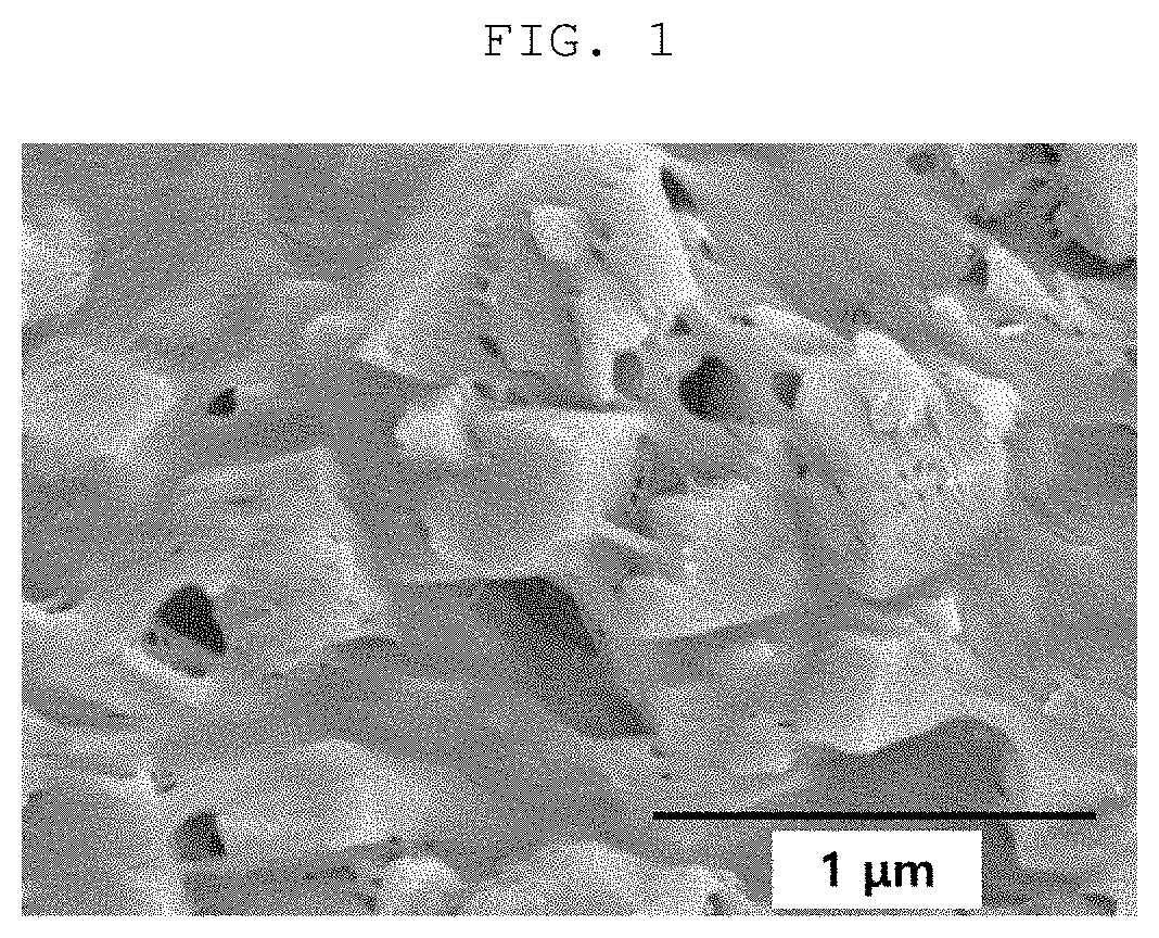
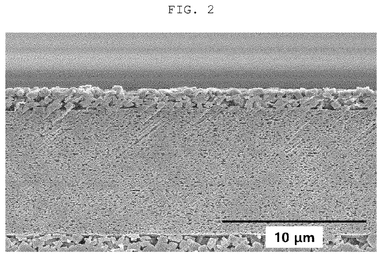
[0109]The prepared dispersion liquid was bar-coated on both surfaces of a polyethylene film (porosity of 41%) having a thickness of 9 μm and drying was performed. A coating thickness of each surface was 1.2 μm. An average pore size and porosity of the manufactured separator were 0.04 μm and 45%, respectively, and a porosity of the coating layer was 56%.

[0110]FIGS. 1 and 2 are SEM photographs obtained by imaging the inorganic composite layer and a cross section of the separator according to Example 1. It could be appreciated from FIG. 1 that the particles were fixed by entanglement of the one-dimensional inorganic materials in the surface of the inorganic composite layer of the separator of...

example 2

[0118]Example 2 was performed in the same manner as that of Example 1 except that the content of the boehmite nanowire in the manufacturing of the separator was 10 parts by weight. The results are shown in Table 1.

example 3

[0119]Example 3 was performed in the same manner as that of Example 1 except that the content of the boehmite nanowire in the manufacturing of the separator was 15 parts by weight. The results are shown in Table 1.


PUM

PropertyMeasurementUnit
lengthaaaaaaaaaa
diameteraaaaaaaaaa
sizeaaaaaaaaaa

Abstract

The present invention relates to an electrochemical device capable of securing battery safety and improving battery performance by including a new separator having excellent thermal stability, excellent electrochemical stability, excellent lithium ion conductivity, and a preferred rate of electrolyte impregnation as compared with a polyolefin-based organic/inorganic composite porous separator according to the related art.

Description

CROSS-REFERENCE TO RELATED APPLICATIONS[0001]This application claims priority to Korean Patent Application No. 10-2020-0083703 filed Jul. 7, 2020 and Korean Patent Application No. 10-2021-0074546 filed Jun. 9, 2021, the disclosures of which are hereby incorporated by reference in their entireties.BACKGROUND OF THE INVENTIONField of the Invention[0002]The following disclosure relates to a separator and an electrochemical device using the same, and more particularly, to a separator which has significantly low thermal contraction and minimizes an increase in resistance even at a high temperature as compared with a separator having a porous inorganic particle layer formed on a porous substrate according to the related art, and an electrochemical device using the same.Description of Related Art[0003]Recently, in accordance with a high capacity and a large size of a secondary battery for application in an electric vehicle or the like, it is significantly important to secure safety of the ...

Claims


Application Information

Patent Timeline
Patent Type & Authority Applications(United States)
IPC IPC(8): H01M50/451H01M10/0525H01M50/403H01M50/491
CPCH01M50/451H01M50/491H01M50/403H01M10/0525H01M50/431H01M50/443H01M50/411H01M50/449H01M50/497H01M50/489H01M50/417H01M50/434H01M50/44H01M50/454H01M50/457H01M10/4235H01G11/52Y02E60/10Y02T10/70
Inventor JI, SANG YOONKIM, YUN BONGLEE, DONG YEON
Owner SK INNOVATION CO LTD
Why Eureka
Try Eureka