Raman spectroscopy method and apparatus

Pending Publication Date: 2022-02-10
UNIVERSITY OF NOTTINGHAM
View PDF2 Cites 2 Cited by
  • Summary
  • Abstract
  • Description
  • Claims
  • Application Information

AI Technical Summary

Benefits of technology

[0018]The apparatus may further comprise recombination optics arranged to spatially recombine different wavelengths of the filtered portion of the emitted radiation before coupling into the detector. Advantageously, this means that the filtered portion of the emitted radiation can be focused down to a smaller spatial spot size which enables the use of a smaller detector active area whilst still collecting all of the available light. This is advantageous because detector bandwidth increases as the detector active area is reduced such that the recombination optics allow for a faster detector to be employed—thereby resulting in a reduction in overall acquisition time for the Raman spectral map. The recombination optics may comprise a pair of pris

Problems solved by technology

However, a major source of noise for many samples arises from laser-excited fluorescence emission, which is a concurrent phenomenon with Raman scattering.
Nevertheless, this approach for fluorescence suppression may still not be sufficient for a range of systems such as pigmented samples (e.g. pigmented biological samples, art and archeology artefacts, geology, etc.).
Optical gating techniques typically use an optical Kerr Gate or an iCCD camera and achieve high fluorescence suppression and high-spectral resolution, but can require long acquisition times. While optical Kerr gating offers a high temporal resolution and choice of excitation wavelength, it requires a complex system that includes powerful pulsed laser systems to activate

Method used


Image

  • Raman spectroscopy method and apparatus
  • Raman spectroscopy method and apparatus
  • Raman spectroscopy method and apparatus

Examples


Embodiment Construction

[0042]Embodiments will now be described by way of example only, with reference to the accompanying drawings, in which:

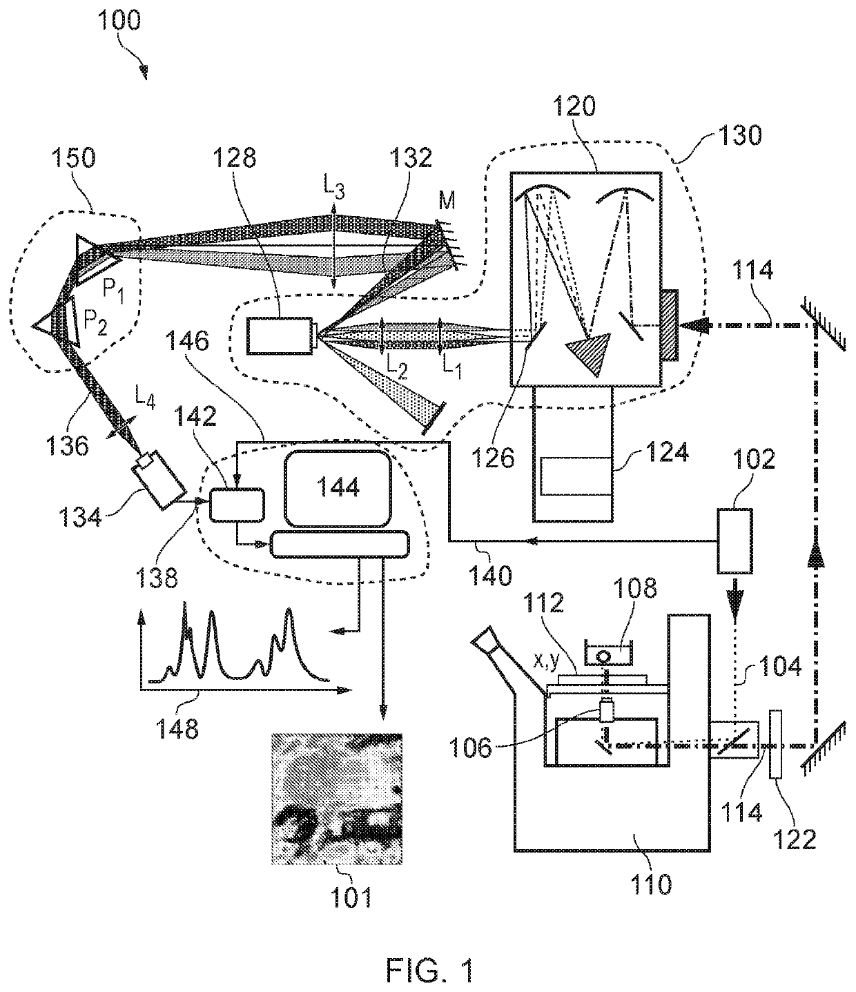
[0043]FIG. 1 is a schematic illustration of an apparatus for acquiring data to produce a time-gated Raman spectral map in accordance with the present disclosure;

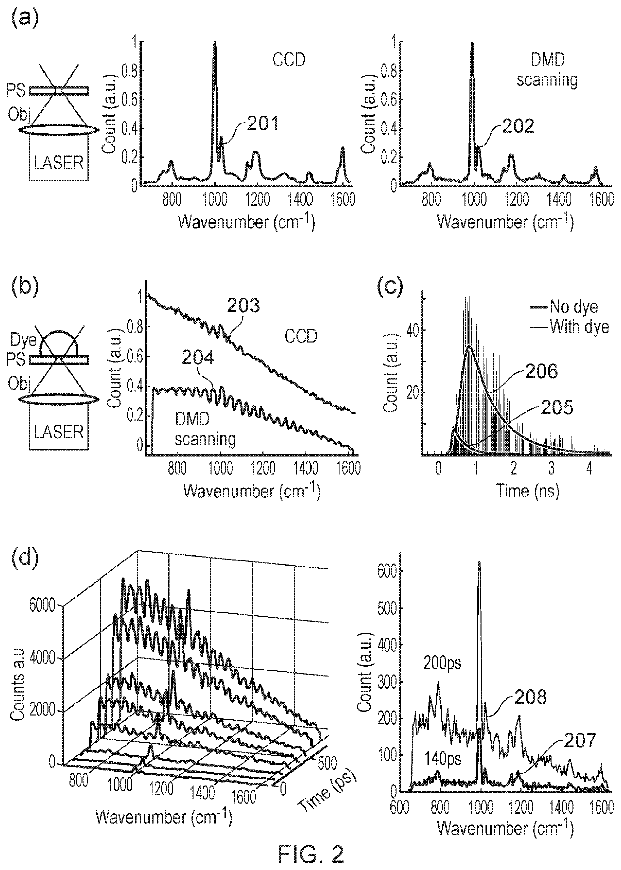
[0044]FIG. 2 shows a comparison between time-gated Raman spectra acquired with an apparatus according to the present disclosure and Raman spectra acquired with a conventional CCD without time gating;

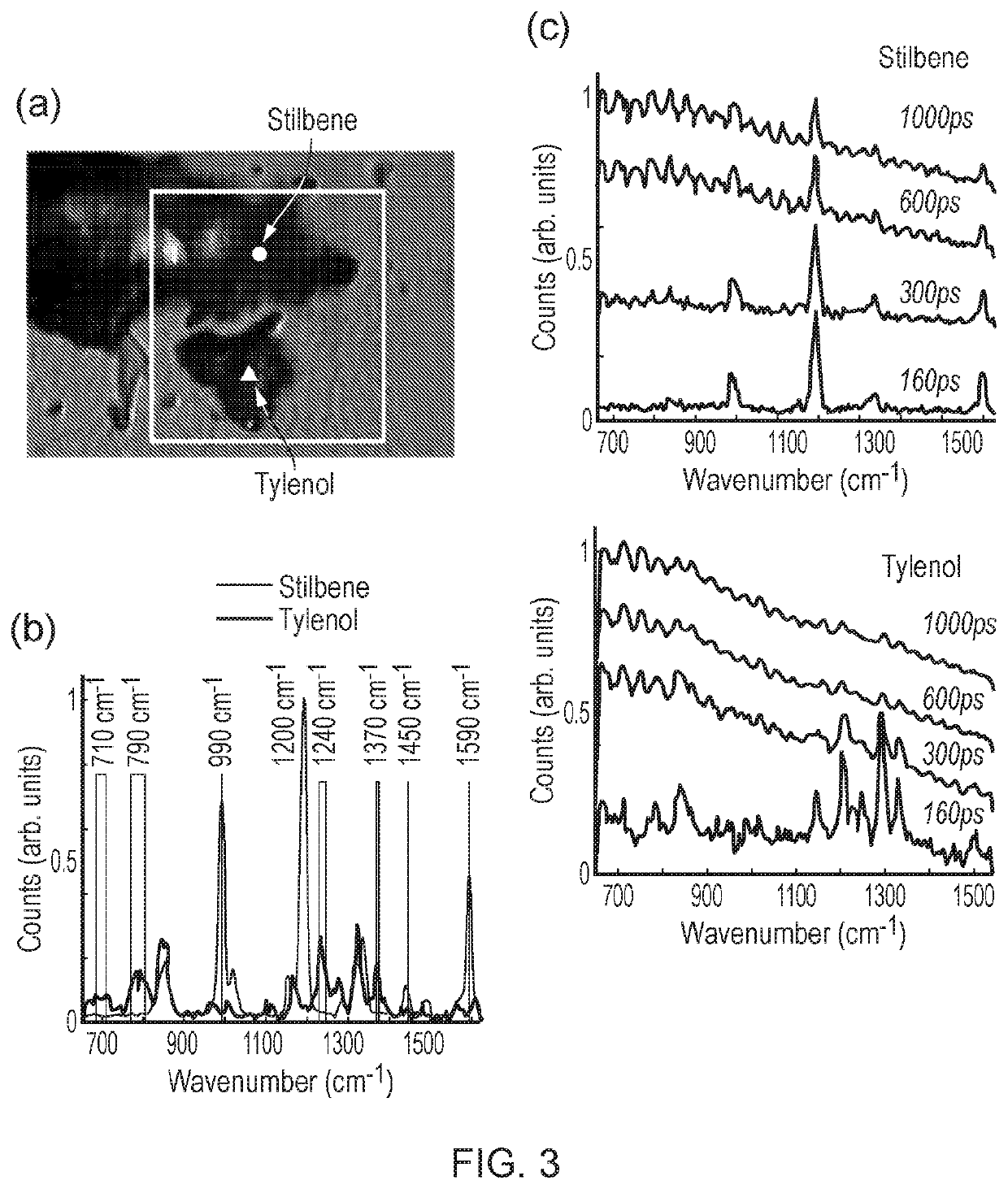
[0045]FIG. 3 shows time-gated Raman spectra acquired with an apparatus according to the present disclosure;

[0046]FIG. 4 shows time-gated Raman spectral maps obtained from measurements made with an apparatus according to the present disclosure;

[0047]FIG. 5 shows a time-gated Raman spectral map of a sample comprising two material species obtained from measurements made with an apparatus according to the present disclosure;

[0048]FIG. 6 is a flow chart corresponding to a method according to the present disclosure;

[004...


PUM


Abstract

Apparatus and methods for acquiring a Raman spectral map of a sample including a material species. The apparatus includes: a pulsed illumination source providing pulsed illumination radiation for exciting the sample and producing scattered radiation; a microscope objective focusing the pulsed illumination radiation onto a region of the sample corresponding to a data point of the map, and collecting emitted radiation from the region; a translation stage translating the sample relative to the microscope objective in at least two directions; a spectral filter spectrally filtering the emitted radiation collected by the objective to obtain a filtered portion of radiation corresponding to a characteristic Raman spectral feature of the material species; a detector receiving the filtered portion and providing output electrical pulses indicative thereof; and readout electronics applying a time gate to the output electrical pulses to distinguish detection events corresponding to the Raman scattered radiation from events associated with photoluminescence.

Description

FIELD OF THE INVENTION[0001]The invention relates to Raman spectroscopy, and in particular to an apparatus and a method for the acquisition of a Raman spectral map of a sample.BACKGROUND[0002]Raman micro-spectroscopy is a powerful tool for mapping molecular properties of samples with diffraction limited spatial resolution. However, a major source of noise for many samples arises from laser-excited fluorescence emission, which is a concurrent phenomenon with Raman scattering. The fluorescence emission leads to a background signal that can be, in some cases, orders of magnitude higher than the Raman signal itself. If the relatively weak Raman signal is of the same order (or smaller) as the shot-noise caused by the fluorescence signal (i.e. square root of fluorescence intensity), then the Raman signal is lost.[0003]Many techniques have been proposed over the years to counteract the effects of fluorescence emission. While computational techniques cannot eliminate the fundamental shot-no...

Claims


Application Information

Patent Timeline
IPC IPC(8): G01N21/65G02B21/02G02B21/26G02B21/36G02B21/16
CPCG01N21/65G02B21/02G02B21/26G02B21/365G01N2201/021G01N2201/0636G01N2201/0635G01N2201/0634G01N2201/06113G02B21/16G01J3/44G01J3/4406G01J3/021G01J3/0229G01J2003/1213
Inventor NOTINGHER, IOANCORDEN, CHRISTOPHERSHIPP, DUSTIN
Owner UNIVERSITY OF NOTTINGHAM
Why Eureka
Try Eureka