
Source Switch Split LNA Design with Thin Cascodes and High Supply Voltage

a source switch and cascode technology, applied in the field of amplifiers, can solve the problems of affecting the operation of the receiver front end, the magnitude of the voltage that occurs across the terminals of output transistors, and the overall receiver performance degradation, so as to achieve the effect of improving the operation of the lna, reducing the distortion, and reducing the distortion

Active Publication Date: 2022-06-23
PSEMI CORP
View PDF4 Cites 0 Cited by
  • Summary
  • Abstract
  • Description
  • Claims
  • Application Information

AI Technical Summary

Benefits of technology

The patent describes a circuit design that improves the performance of a low-noise amplifier (LNA) in a wireless communication device. The circuit has two LNA branches, each containing a cascode pair of field effect transistors (FETs) to amplify signals. By controlling the ON and OFF states of the LNA branches using a high-voltage tolerant switch, the circuit can achieve improved performance in terms of noise figure and third order intercept. This design provides a significant advantage over prior art LNA circuits.

Problems solved by technology

Any noise or distortion in the input to the LNA will get amplified and cause degradation of the overall receiver performance.
One issue that arises with the use of such a design is the magnitude of the voltage that occurs across the terminals of an output transistor 208, 212 when the respective LNA 202, 204 is turned OFF.
Such conditions can adversely impact the operation of the receiver front end, and in some cases, cause the receiver front end to completely fail.

Method used


Image

  • Source Switch Split LNA Design with Thin Cascodes and High Supply Voltage
  • Source Switch Split LNA Design with Thin Cascodes and High Supply Voltage
  • Source Switch Split LNA Design with Thin Cascodes and High Supply Voltage

Examples


embodiment

Detailed Embodiment

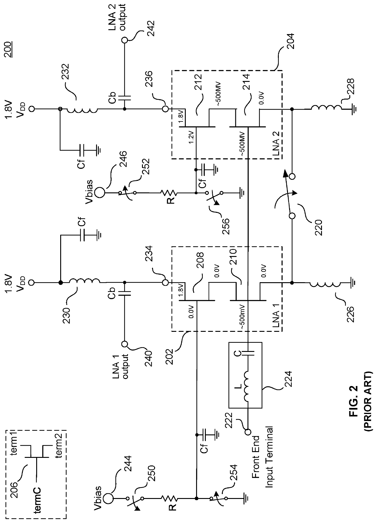
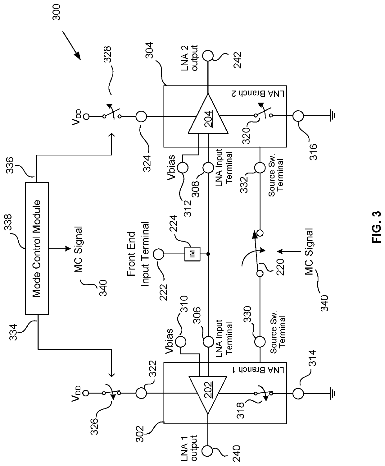
[0039]FIG. 4A shows additional details of each of the two LNA branches 302, 304 of FIG. 3. As should be clear, the interior details for the two LNA branches 302, 304 are similar in many (but not all) respects to a conventional LNA (compare FIG. 2; note that labels for the AC filter capacitors and DC blocking capacitors are omitted for clarity). The amplifier-branch control switches 326, 328 and source switch 220 are shown in FIG. 4A to be configured for operation of the receiver front end 300 in single mode 2 (i.e., LNA branch 304 is ON and LNA branch 302 is OFF). Accordingly, the control signal 334 causes amplifier-branch control switch 326 to be open and the control signal 336 causes amplifier-branch control switch 328 to be closed. In the illustrated example, the mode control signal 340 to the source switch 220 causes the source switch 220 to be closed in both single mode 1 (as shown in FIG. 3) and single mode 2 (as shown in FIG. 4A). The transistors in FIG. 4A...


PUM


Abstract

A receiver front end capable of receiving and processing intraband non-contiguous carrier aggregate (CA) signals using multiple low noise amplifiers (LNAs). Cascode circuits, each having a “common source” configured input FET and a “common gate” configured output FET, serve as the LNAs. An amplifier-branch control switch, configured to withstand relatively high voltage differentials by means of a relatively thick gate oxide layer and coupled between a terminal of the output FET and a power supply, controls the ON and OFF state of each LNA while enabling use of a relatively thin gate oxide layer for the output FETs, thus improving LNA performance. Some embodiments may include a split cascode amplifier and / or a power amplifier.

Description

BACKGROUND(1) Technical Field[0001]Various embodiments described herein relate to amplifiers and more particularly to low noise amplifiers for use in communications equipment.(2) Background[0002]The front end of a communications receiver typically includes a low noise amplifier (“LNA”) that is responsible for providing the first stage amplification to a signal received by the receiver. The operational specifications of the LNA are very important to the overall quality of the receiver. Any noise or distortion in the input to the LNA will get amplified and cause degradation of the overall receiver performance. Accordingly, the sensitivity of a receiver is, in large part, determined by the quality of the front end and of the LNA in particular.[0003]In some cases, the LNA is required to operate over a relatively broad frequency band and to amplify signals having several modulated baseband or intermediate frequency (IF) signals. One example of such a situation is reception of an intraban...

Claims


Application Information

Patent Timeline
Patent Type & Authority Applications(United States)
IPC IPC(8): H03F3/193
CPCH03F3/193H03F2200/294H03F2200/451H03F1/223H03F3/68H03F3/72
Inventor GOLAT, JOSEPHKOVAC, DAVID
Owner PSEMI CORP
Learn More