
High-throughput microfluidic chip having parallelized constrictions for perturbing cell membranes

a microfluidic chip and parallelization technology, applied in biochemistry apparatus and processes, laboratory glassware, tissue/virus culture apparatus, etc., can solve the problems of insufficient throughput rate, insufficient simple and efficient fabrication, and easy clogging of constrictions of known intracellular payload delivery systems

Pending Publication Date: 2022-06-30
SQZ BIOTECH CO
View PDF1 Cites 0 Cited by
  • Summary
  • Abstract
  • Description
  • Claims
  • Application Information

AI Technical Summary

Benefits of technology

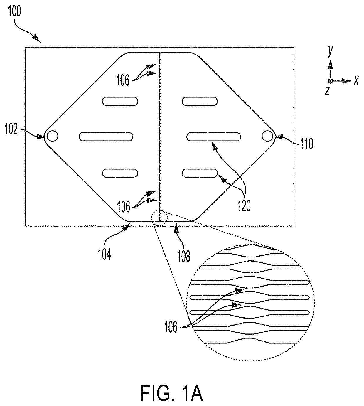
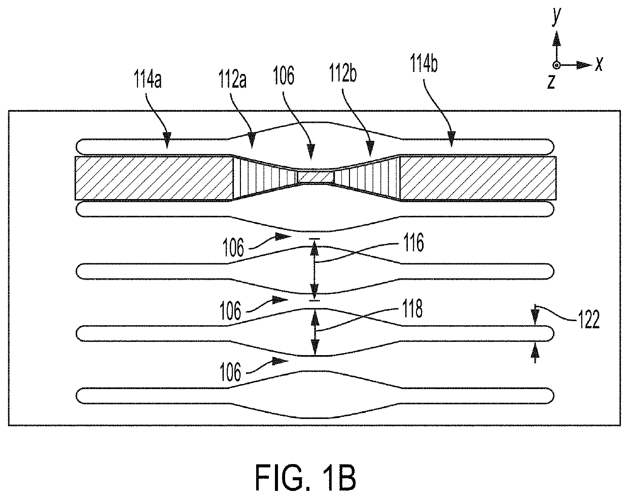
This patent is about improving systems and methods for delivering payloads into cells using microfluidic chips. The patent describes the use of microfluidic cell-constricting chips with high throughput rates and low clogging rates. The chips have improved geometric configurations, including parallelized constrictions, increased cross-sectional constriction area, and constrictions with uniform flow velocity and patterns. These improvements ensure high throughput and low clogging, while also minimizing the likelihood and extent of constriction clogging. Overall, the patent provides effective means for delivering payloads into cells using microfluidic technology.

Problems solved by technology

However, known systems for intracellular payload delivery are prone to clogging of constrictions, have insufficient throughput rates, and are not sufficiently simple and efficient to fabricate.

Method used


Image

  • High-throughput microfluidic chip having parallelized constrictions for perturbing cell membranes
  • High-throughput microfluidic chip having parallelized constrictions for perturbing cell membranes
  • High-throughput microfluidic chip having parallelized constrictions for perturbing cell membranes

Examples


example 1

[0148]Performance of different chips was compared, where constrictions of a first set of two chips in parallel were 4 μm in width, and constrictions of a second set of two chips in parallel were 4.5 μm in width. Each chip contained 75 constrictions arranged in parallel. For all chips, constriction length was 10 μm. For all chips, a pressure of 50 PSI and a temperature of 2-8° C. was used. For all chips, the blood product Hemacare LP was used at a concentration of 7.20×10⁷ cells / mL. For all chips, a delivery media of RPMI and a delivery material of 0.01 mg·ML 3 kDa Dextran AF 680 was used.

[0149]Performance of the chips is shown in Table 1 below:

TABLE 1ChipNucleoCounter ®Live Cell RecoveryTotal LiveConstrictionNC-200 ™ ViabilityThrough 2 hourCells PassedWidthPost-Squeeze at T0Incubationthrough chips  4 μm72.4%43.6%2.88e94.5 μm79.6%64.5%3.96e9

example 2

[0150]Performance of a chip having 75 constrictions arranged in parallel, each constriction having a width of 4 μm and etch depth of 66 μm was tested. The chip performed a microfluidic squeeze under the following pressures: 40 PSI, 50 PSI, and 60 PSI. These three runs or “squeezes” were plotted against three control squeezes: Control 1 (chip with constrictions measuring 30 μm length, 4 μm width, and 20 μm depth tested at 60 PSI), Control 2 (addition of dextran to cell suspension with no microfluidic squeezing), Control 3: (no addition of dextran and no microfluidic squeezing), to show the percentage of live B cells, percentage of dextran delivery, and relative mean fluorescence intensity as shown in FIG. 11.

[0151]The graphs on the right in FIG. 11 are histograms showing fluorescence analysis of the uptake of dextran by cells under different conditions. The top three histograms represent squeezes under different pressures: 40 PSI, 50 PSI, and 60 PSI. “STD” represents squeeze conditio...

example 3

[0154]A chip was fabricated having 950 constrictions arranged in parallel, each constriction having a width of 4.5 μm, a length of 10 μm, and a etch depth of 80 μm. The overall size of the chip was 30 mm in length, 20 mm in width, and 1225 μm in height (thickness). The chip included an inlet fluidic port spaced 24 mm from an outlet fluidic port, each port having a diameter of 2.00 mm. The chip included a silicon substrate of 600 μm in height (thickness) and a glass top layer of 600 μm in thickness.

[0155]Target constriction dimensions for fabricating the chip were 4.50±0.20 μm for constriction width, 10±1 μm for constriction length, and 80±2 μm for constriction height (depth).

[0156]Specifications for fabricating the chip were as shown in Table 2 below:

TABLE 2SpecificationTargetMinMaxGlass wafer625600650thickness, μmSilicon wafer600575625thickness, μmTotal device122511751275thickness, μmConstriction width, μm4.504.304.70Variation in0−0.200.20constriction width, μmConstriction depth, μ...


PUM

PropertyMeasurementUnit
cross-sectional widthaaaaaaaaaa

Abstract

A microfluidic chip for causing the delivery of a payload to a cell comprises a plurality of constrictions configured to allow a cell suspension to flow through one or more of the plurality of constrictions from a first fluid flow region to a second fluid flow region within the microfluidic chip, wherein a cross-sectional width of each of the plurality of constrictions is less than a diameter of cells in the cell suspension, such that membranes of the cells are perturbed when passing through the constrictions such that a payload is able to pass through the perturbed cell membranes, and wherein a quotient of a cross-sectional area over a cross-sectional perimeter of each of the plurality of constrictions is greater than greater than or equal to 0.5 μm.

Description

CROSS-REFERENCE TO RELATED APPLICATION(S)[0001]This application claims benefit claims the benefit of U.S. Provisional Application No. 63 / 131,430, filed Dec. 29, 2020, the entire contents of which are hereby incorporated herein by reference.FIELD[0002]The present disclosure relates to delivery of a payloads into cells, and more specifically to microfluidic constricting channels that may perturb cell membranes to allow the passage of payloads through the perturbed membranes.BACKGROUND[0003]The controlled delivery of various materials into cells is important in the developing medical field of cell therapy. For example, various research and therapeutic applications may include the delivery of peptides, nucleic acids, proteins, small molecules, and nanomaterials through cell membranes and into cells. As discussed in WO2013059343, WO2015023982, PCT / US2015 / 058489, PCT / US2015 / 060689, and PCT / US2016 / 13113, constricting microfluidic channels may be used to deliver compounds and other payloads...

Claims


Application Information

Patent Timeline
Patent Type & Authority Applications(United States)
IPC IPC(8): C12M3/06C12M1/26B01L3/00
CPCC12M23/16C12M33/12B01L2200/12B01L2300/0819B01L3/502707B01L3/502746B01L3/502761B01L2200/0663B01L2400/0487B01L2400/086C12M35/04
Inventor DADGAR, MAISAMHANSON, JACQUELYN L. SIKORASHAREI, ARMON R.
Owner SQZ BIOTECH CO
Learn More