Resist composition and method of forming resist pattern

a resist composition and composition technology, applied in the direction of microlithography exposure apparatus, photomechanical equipment, instruments, etc., can solve the problem of difficulty in achieving all of the above characteristics

Pending Publication Date: 2022-06-30
TOKYO OHKA KOGYO CO LTD
View PDF0 Cites 0 Cited by
  • Summary
  • Abstract
  • Description
  • Claims
  • Application Information

AI Technical Summary

Benefits of technology

[0011]The present invention has been made in consideration of the above circumstances, and an object of the present invention is to provide a resist composition with which high sensitivity is further achieved and a resist pattern having good CDU and good resolution can be formed, and a method of forming a resist pattern using the resist composition.
[0016]According to the present invention, it is possible to provide a resist composition with which high sensitivity is further achieved and a resist pattern having good CDU and good resolution can be formed, and a method of forming a resist pattern using the resist composition.

Problems solved by technology

However, in the resist composition containing such a conventional resin as described above, in a case where the sensitivity to an exposure light source was increased, a desired resist pattern shape or the like was not easily obtained, and thus it was difficult to achieve all of the above characteristics.

Method used


Image

  • Resist composition and method of forming resist pattern
  • Resist composition and method of forming resist pattern
  • Resist composition and method of forming resist pattern

Examples


synthesis example 1

of Polymeric Compound

Synthesis Example of Polymeric Compound (A-1)

[0826]18.9 g of a monomer (m-a0-1), 10.0 g of a monomer (m-a10-1 pre), and 3.86 g of azobis (isobutyric acid) dimethyl (V-601) as a polymerization initiator were dissolved in 43.6 g of methyl ethyl ketone (MEK) to prepare a dropping solution. 11.6 g of MEK was added to a three-necked flask connected with a thermometer, a reflux tube, and a nitrogen feeding tube, heated to 85° C. in a nitrogen atmosphere, and the above dropping solution was added dropwise over 4 hours. After completion of the dropwise addition, the reaction solution was stirred at 85° C. for 1 hour. Then, the reaction solution was cooled to room temperature. Next, 12.2 g of acetic acid and 175 g of methanol were added to the obtained polymerization solution, and a deprotection reaction was carried out at 30° C. for 8 hours. After completion of the reaction, the obtained reaction solution was precipitated in 2,600 g of heptane, followed by washing. The ...

synthesis examples 2 to 25

of Polymeric Compounds

[0828]Polymeric compounds (A-2) to (A-25) having composition ratios shown in Table 1 were synthesized in the same manner as in Synthesis Example 1 of the polymeric compound by using the compounds (m-a0-1) to (m-a0-6) shown above and compounds (m-a10-1 pre), (m-a10-2 pre), (m-a10-3 pre), (m-a1-1) to (m-a1-3), and (m-a8), (m-a2), and (m-a3) shown below.

[0829]With respect to the obtained polymeric compounds, the copolymerization composition ratio (the ratio (molar ratio) between constitutional units, each of which is derived from a monomer) in the polymeric compound, which was determined by 13C-NMR, the weight average molecular weight (Mw) in terms of standard polystyrene equivalent value, which was determined by GPC measurement, and the polydispersity (Mw / Mn) are shown together in Table 1.

[0830]It is noted the constitutional units each represented by Chemical Formulae (a10-1-1), (a10-1-2), and (a10-1-3), which constitute the above-described copolymer, are constit...


PUM

PropertyMeasurementUnit
solubilityaaaaaaaaaa
wavelengthaaaaaaaaaa
energyaaaaaaaaaa

Abstract

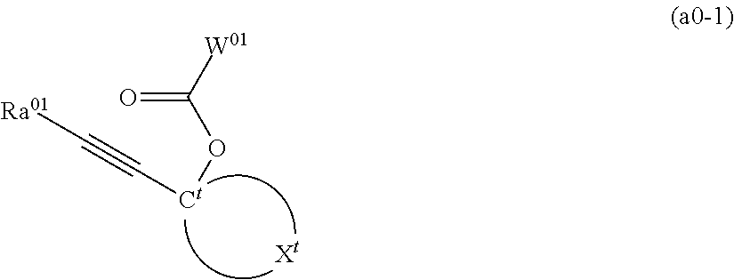
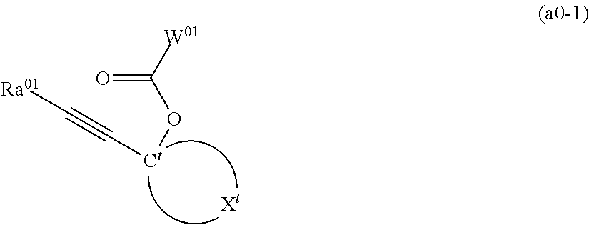
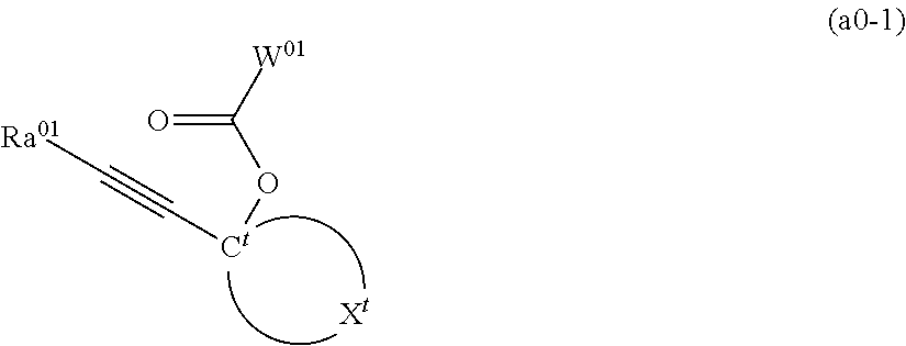
A resist composition containing a polymeric compound having a constitutional unit (a01) derived from a compound represented by General Formula (a0-1). In the formula, W01 represents a polymerizable group-containing group, Cy represents a tertiary carbon atom, Xt represents a group that forms a monocyclic or polycyclic hydrocarbon group together with Ct, provided that part or all of hydrogen atoms contained in this monocyclic or polycyclic hydrocarbon group may be substituted with a substituent, and part of carbon atoms constituting a ring may be substituted with a hetero atom, and Ra01 represents a linear, branched, or cyclic aliphatic hydrocarbon group

Description

BACKGROUND OF THE INVENTIONField of the Invention[0001]The present invention relates to a resist composition and a method of forming a resist pattern.[0002]Priority is claimed on Japanese Patent Application No. 2020-214127, filed on Dec. 23, 2020, and Japanese Patent Application No. 2021-024651, filed on Feb. 18, 2021, the contents of which are incorporated herein by reference.Description of Related Art[0003]In recent years, in the production of semiconductor elements and liquid crystal display elements, advances in lithography techniques have led to a rapid progress in the field of pattern fining. Typically, these pattern fining techniques involve shortening the wavelength (increasing the energy) of the light source for exposure.[0004]Resist materials for use with these types of light sources for exposure require lithography characteristics such as a high resolution capable of reproducing a fine-sized pattern, and a high level of sensitivity to these types of light sources for expo...

Claims


Application Information

Patent Timeline
Patent Type & Authority Applications(United States)
IPC IPC(8): G03F7/004G03F7/20G03F7/32G03F7/40
CPCG03F7/0045G03F7/40G03F7/322G03F7/20G03F7/0397G03F7/004G03F7/0382G03F7/0392
Inventor IKEDA, TAKUYA
Owner TOKYO OHKA KOGYO CO LTD
Why Eureka
Try Eureka