
Liquid assisted additive manufacturing of a superalloy component

a superalloy and additive manufacturing technology, applied in the direction of additive manufacturing with solid and fluid, welding/cutting media/materials, metal-working apparatus, etc., can solve the problems of high ′ forming nickel-base superalloy materials, additive manufacturing or welded superalloy components are sensitive to strain-age cracking,

Pending Publication Date: 2022-07-21
SIEMENS ENERGY INC
View PDF0 Cites 0 Cited by
  • Summary
  • Abstract
  • Description
  • Claims
  • Application Information

AI Technical Summary

Benefits of technology

The invention is about a method for making a high-quality low melt superalloy powder using a special composition that reduces the amount of microcracking during heat treatment. The method involves mixing low melt and high melt superalloy powders together, and then heating them to a specific temperature to create the desired composition. This results in a powder that is easier to use and has improved quality compared to powders made using a different method. The special composition also helps to fill solidification cracks in the powder, which further improves its quality. Overall, this method creates a high-quality low melt superalloy powder that is more suitable for use in various applications.

Problems solved by technology

However, additively manufacturing and / or welding of high γ′ forming nickel-base superalloy materials has been known to be difficult as such superalloys experience solidification and grain boundary liquation cracking problems during such processes.
Further, during subsequent heat treatments such additively manufactured or welded superalloy components are sensitive to strain-age cracking.

Method used


Image

  • Liquid assisted additive manufacturing of a superalloy component
  • Liquid assisted additive manufacturing of a superalloy component
  • Liquid assisted additive manufacturing of a superalloy component

Examples


Embodiment Construction

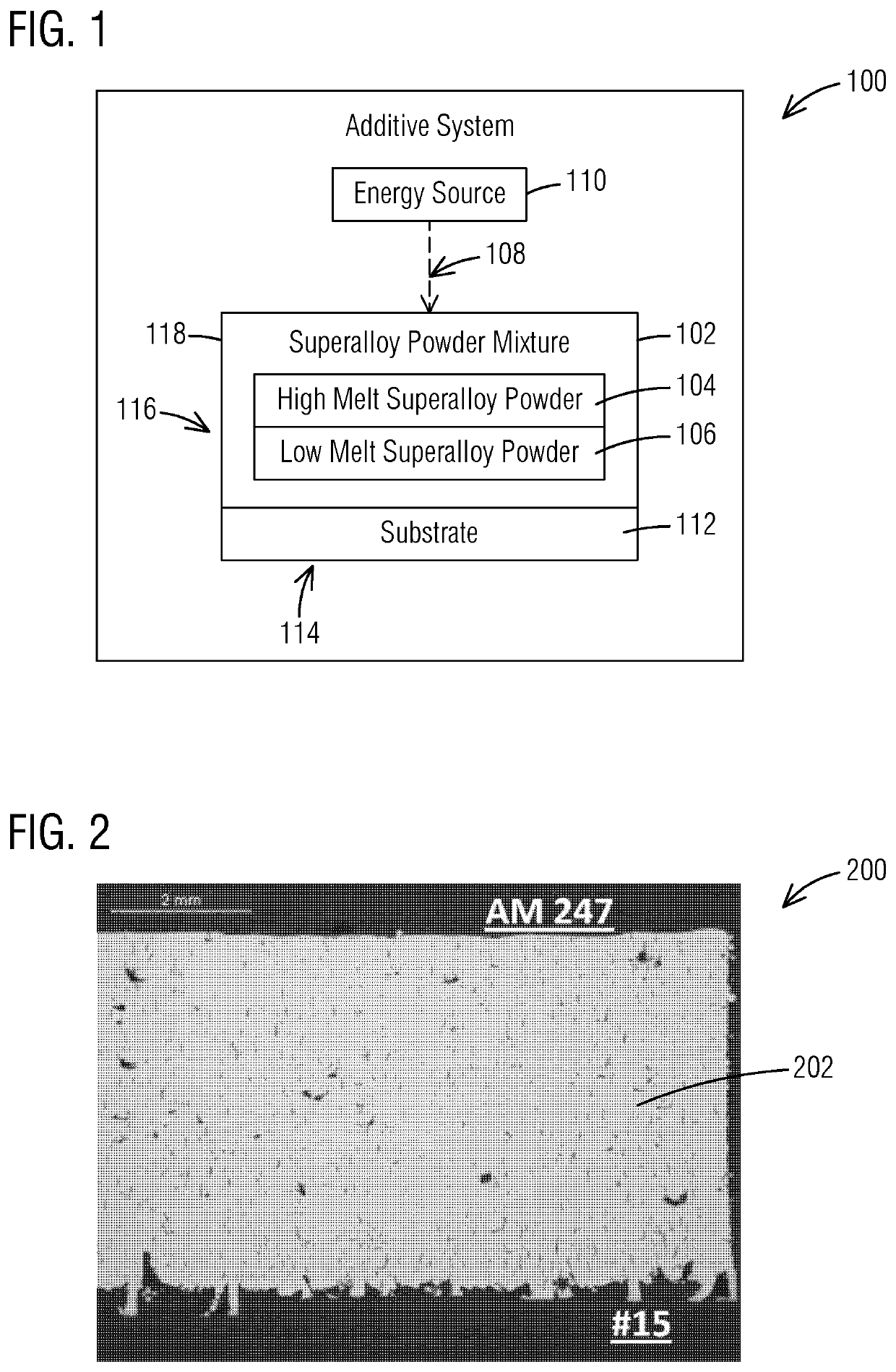
[0111]Various technologies that pertain to systems, methods and materials that facilitate additively manufacturing (and / or welding) components made from superalloy materials will now be described with reference to the drawings, where like reference numerals represent like elements throughout. Before any embodiments of the invention are explained in detail, it is to be understood that the invention is not limited in its application to the details of construction and the arrangement of components set forth in this description or illustrated in the following drawings. The invention is capable of other embodiments and of being practiced or of being carried out in various ways. Also, it is to be understood that the phraseology and terminology used herein is for the purpose of description and should not be regarded as limiting.

[0112]Example embodiments of one or more inventions described herein are directed to making components comprising nickel-base superalloys including greater than 40%...


PUM

PropertyMeasurementUnit
Temperatureaaaaaaaaaa

Abstract

A method is provided that facilitates additive manufacturing a superalloy component using a liquid assisted additive manufacturing process. The method includes successively depositing and fusing together layers of a superalloy powder mixture comprising a high melt superalloy powder and a low melt superalloy powder to build up an additive portion of the superalloy component. The method may further include heat treating the additive portion to form a homogenized base alloy of which the additive portion is comprised, which base alloy has a chemistry defined by the superalloy powder mixture. Each of the high melt superalloy powder, the low melt superalloy powder, and the superalloy powder mixture may have a nickel content by weight greater than 40% and have an aluminum content by weight of greater than 1.5%. The low melt superalloy powder may include at least 5% by weight of tantalum, and the high melt superalloy powder may include less than half the content by weight percent of tantalum compared to the content by weight percent of tantalum in the low melt superalloy powder.

Description

BACKGROUND[0001]The present disclosure relates generally to the field of additive manufacturing and welding, and more particularly, to additively manufacturing and / or welding components made of difficult-to-weld superalloys used in gas turbines and other high temperature applications.[0002]Nickel-base superalloys are metal alloys capable of being used to form gamma-prime (γ′) precipitation-strengthened metal parts that have a favorable combination of mechanical strength and resistance to thermal fatigue, oxidation, type I or type II corrosion, and thermal creep deformation. High γ′ forming nickel-base superalloys are typically used in high temperature applications (e.g., above 950° C.). For example, parts casted from such superalloys may include blades, guide vanes and other hot gas path components that are used in aerospace, marine, and industrial gas turbine engines. However, additively manufacturing and / or welding of high γ′ forming nickel-base superalloy materials has been known...

Claims


Application Information

Patent Timeline
IPC IPC(8): B22F10/62B22F1/105B22F12/41B22F10/28B22F5/04B22F10/64B33Y10/00B33Y40/20B33Y70/00B33Y80/00
CPCB22F10/62B22F1/105B22F12/41B22F10/28B22F5/04B22F10/64B22F2301/205B33Y40/20B33Y70/00B33Y80/00B22F2301/052B22F2301/15B33Y10/00C22C1/0433C22C19/00B22F10/25B22F10/18B23K35/304B23K26/342B22F2998/10C22C19/055C22C19/056C22C19/057C22C19/058C22F1/10C22C30/00B23K35/3033B23K26/21B23K2101/001B23K2103/26Y02P10/25B22F3/10B23K35/0261B29C64/165B23K2103/08B22F10/14B22F1/05B22F2304/10B22F1/09C22C2202/00
Inventor OZBAYSAL, KAZIMKAMEL, AHMED
Owner SIEMENS ENERGY INC
Learn More