Method of producing fuel cell

Pending Publication Date: 2022-09-22
HONDA MOTOR CO LTD
View PDF0 Cites 0 Cited by
  • Summary
  • Abstract
  • Description
  • Claims
  • Application Information

AI Technical Summary

Benefits of technology

The patent describes a method of manufacturing a fuel cell that can activate quickly and efficiently, even when the specifications of the membrane electrode assembly change. The method involves using superheated steam to remove a barrier layer and improve the diffusion performance of the gas diffusion layer, which allows for better activation of the cathode electrode. This method also eliminates the inhibition of oxygen diffusion and exhibits a sufficient activation effect for the oxidation-reduction reaction of the cathode electrode. Overall, this method reduces hydrogen consumption, processing time, and allows for a faster and more effective activation of the fuel cell.

Problems solved by technology

However, it has been found that the activation method disclosed in JP 5587286 B2 cannot provide a sufficient activation effect within an expected processing time for a membrane electrode assembly having different specifications in which a step of joining a catalyst layer and a diffusion layer to both surfaces of an electrolyte membrane is changed.
That is, in the activation method of JP 5587286 B2, although the activation effect of the desorption and adsorption reaction of hydrogen at the anode electrode is excellent, the activation effect of the oxidation-reduction reaction at the cathode electrode may not be sufficient.
However, there is a problem that a large amount of hydrogen gas is required.

Method used


Image

  • Method of producing fuel cell
  • Method of producing fuel cell
  • Method of producing fuel cell

Examples


Embodiment Construction

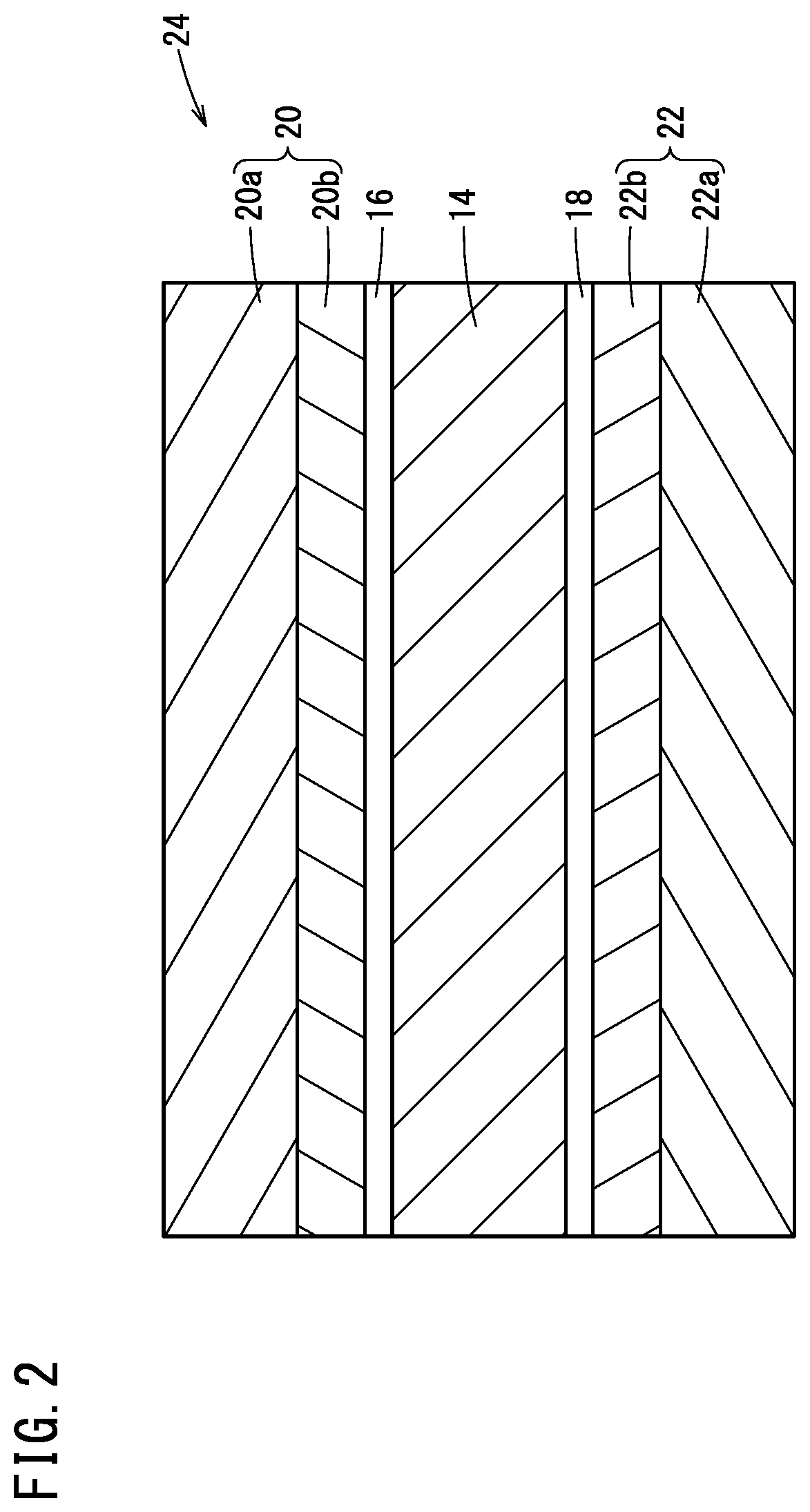
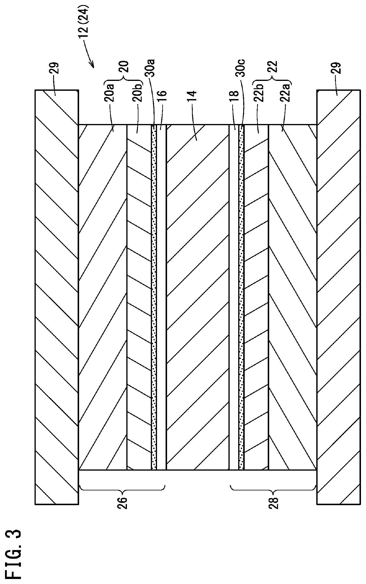
[0018]Steps of a method for manufacturing a fuel cell of the present embodiment proceed in the order of FIGS. 1 to 7. First, a process of forming a membrane electrode assembly 12 shown in FIGS. 1 to 3 will be described.

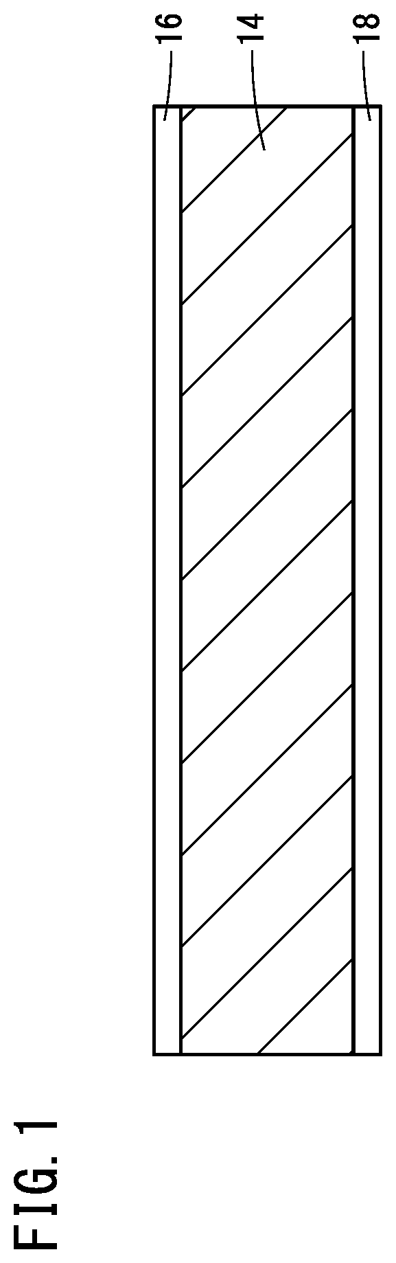
[0019]As shown in FIG. 1, in the first step, an anode catalyst layer 16 is formed on one surface of an electrolyte membrane 14, and a cathode catalyst layer 18 is formed on the other surface of the electrolyte membrane 14. The electrolyte membrane 14 is formed of, for example, a solid polymer electrolyte such as a fluorine-based resin having hydrogen conductivity. The electrolyte membrane 14 is provided as a sheet body wound in a roll shape. The roll-shaped electrolyte membrane 14 is stretched. Ink containing an anode catalyst is applied to one surface of the electrolyte membrane 14. Ink containing a cathode catalyst is applied to the other surface of the electrolyte membrane 14. The electrolyte membrane 14 coated with the ink containing the catalyst is heated at a pr...


PUM


Abstract

The method of manufacturing the fuel cell includes a step of stacking a gas diffusion layer (for example, an anode diffusion layer and a cathode diffusion layer) and a catalyst layer (for example, an anode catalyst layer and a cathode catalyst layer) on an electrolyte membrane, performing heat treatment with pressure and heat to form a membrane electrode assembly, a preliminary treatment step of bringing superheated steam into contact with the membrane electrode assembly, and an aging step of applying a voltage having a predetermined waveform between an anode electrode and a cathode electrode of the membrane electrode assembly subjected to the preliminary treatment step.

Description

CROSS-REFERENCE TO RELATED APPLICATIONS[0001]This application is based upon and claims the benefit of priority from Japanese Patent Application No. 2021-043363 filed on Mar. 17, 2021, the contents of which are incorporated herein by reference.BACKGROUND OF THE INVENTIONField of the Invention[0002]The present invention relates to a method for manufacturing a fuel cell.Description of the Related Art[0003]In a manufacturing process of a fuel cell stack, a catalyst layer and a diffusion layer are bonded to both surfaces of an electrolyte membrane to form a membrane electrode assembly. Next, the membrane electrode assembly is sandwiched between a separator plate having an anode flow path and a separator plate having a cathode flow path to form a power generation cell. Furthermore, tens to hundreds of power generation cells are stacked. Then, the stacked power generation cells are sandwiched between a pair of end plates, and a tightening load is applied in the thickness direction to integ...

Claims


Application Information

Patent Timeline
IPC IPC(8): H01M4/88H01M8/1004
CPCH01M4/8882H01M8/1004Y02P70/50Y02E60/50
Inventor YAMADA, TADAAKI
Owner HONDA MOTOR CO LTD
Why Eureka
Try Eureka