Method for coating a substrate with tantalum nitride

a technology of tantalum nitride and substrate, which is applied in the direction of vacuum evaporation coating, coating, electric discharge tube, etc., can solve the problem of limiting the additional energy required to initiate the plasma to form the coating

Pending Publication Date: 2022-11-03
SAFRAN +2
View PDF0 Cites 0 Cited by
  • Summary
  • Abstract
  • Description
  • Claims
  • Application Information

AI Technical Summary

Problems solved by technology

Continuous bias allows a residual plasma to be maintained when pulses are not applied, a

Method used


Image

  • Method for coating a substrate with tantalum nitride
  • Method for coating a substrate with tantalum nitride

Examples


Embodiment Construction

[0025]The invention will now be described by means of the figures provided by way of illustration and should not be interpreted as limiting the scope of the invention.

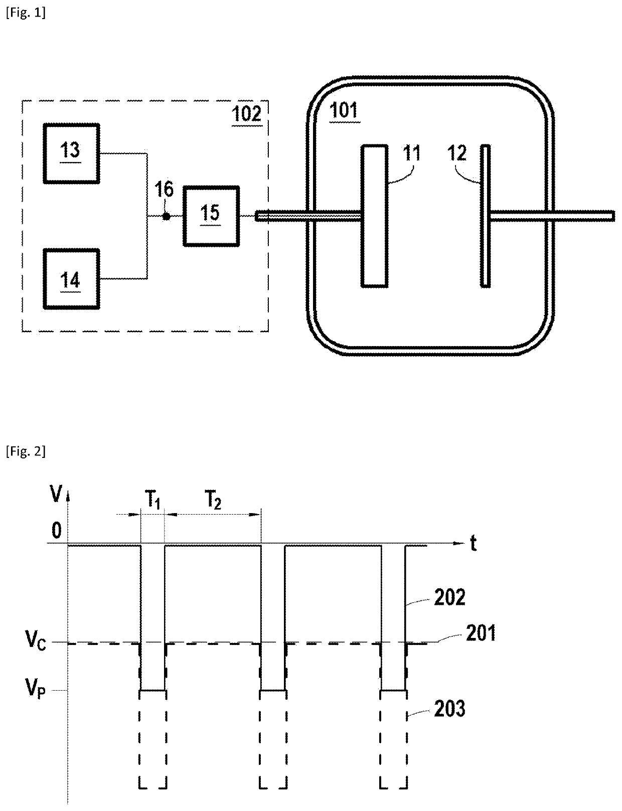
[0026]FIG. 1 schematically represents a device for performing a high-power impulse magnetron sputtering deposition according to an embodiment of the invention.

[0027]The device includes a chamber 101 for receiving a plasma gas, for example consisting of a mixture of argon and nitrogen. The device further comprises a source of plasma gas (not shown) in communication with the chamber 101.

[0028]The chamber 101 comprises a tantalum target 11 constituting the cathode and a substrate 12 to be coated constituting the anode. In an embodiment, the target 11 comprises tantalum in excess of 99 at.%, and preferably in excess of 99.9 at.%. The substrate 12 to be coated is electrically conductive and may vary in nature depending on the intended application as noted above.

[0029]During coating, the target 11 is biased as described abov...


PUM


Abstract

A process for coating a substrate with tantalum nitride by the high-power impulse magnetron sputtering technique, wherein a tantalum target is used and wherein the coating of the substrate is carried out in an atmosphere containing nitrogen, the bias of the target being controlled during the coating by imposing on it the superposition of a continuous bias at a potential between −300 V and −100 V and of a pulsed bias whose pulses have a potential between −1200 V and −400 V.

Description

TECHNICAL FIELD[0001]The invention relates to a process for coating a substrate with at least one layer of tantalum nitride, with a view to replace chromium(VI)-based coatings.PRIOR ART[0002]In order to improve the properties of metal substrates, in particular in terms of resistance to corrosion or to wear, it is known to coat them with a protective layer. As such, chromium(VI) oxide is particularly advantageous in that it has good hardness, high resistance to fatigue and to corrosion, and also good thermal and chemical stability. However, in the context of legal developments and the REACH regulation, these chromium coatings must be replaced. It is therefore necessary to have replacement solutions with at least equivalent physico- chemical properties that are compatible with industrial, economic and environmental requirements.DISCLOSURE OF THE INVENTION[0003]The invention relates to a process for coating a substrate with tantalum nitride by the high-power impulse magnetron sputterin...

Claims


Application Information

Patent Timeline
IPC IPC(8): C23C14/34C23C14/06C23C14/35C23C14/00H01J37/34
CPCC23C14/3485C23C14/0641C23C14/35C23C14/0036H01J37/3405H01J37/3426H01J37/3467H01J2237/332C23C14/345H01J37/3464
Inventor CAVARROC, MARJORIE CHRISTINEGIROIRE, BAPTISTE SIMONTEULE-GAY, LIONELPOULON, ANGÉLIQUE
Owner SAFRAN
Why Eureka
Try Eureka