

Ultrafine particle and production method thereof, production method of ultrafine particle bonded body, and fullerene and production method thereof
a technology of ultrafine particles and production methods, applied in the direction of fullerene, natural mineral layered products, synthetic resin layered products, etc., can solve the problems of insufficient mutual control of bonding ultrafine particles, methods that cannot fully control their formed state, and hardly obtain the unit substance of ultrafine particles by conventional production methods
- Summary
- Abstract
- Description
- Claims
- Application Information
AI Technical Summary
Benefits of technology
Problems solved by technology
Method used
Image

Examples
embodiment 2
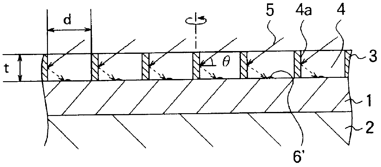
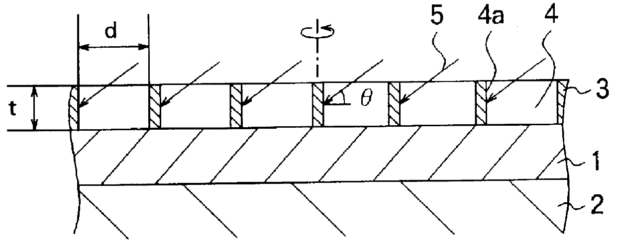
A carbon film was used as the substrate, and an Au mesh (a thickness of 200 .mu.m) having a large number of pores with a diameter of 100 .mu.m was placed as the target material on the carbon film. A Cu mesh as the supporting member on which the above laminate was positioned was placed on a room temperature stage in a vacuum chamber.
An Ar ion beam was irradiated in a slanting direction to the pores' inner walls of the Au mesh for 200 seconds while the carbon film and the Au mesh were being rotated at 2 rpm. The Ar ion beam had an acceleration voltage of 3.0 kV and a beam current of 0.5 mA. The Ar ion beam was irradiated at an incident angle .theta. of 35 degrees. And, the Ar ion beam was irradiated in a vacuum atmosphere (containing Ar) of about 1.times.10.sup.-3 Pa.
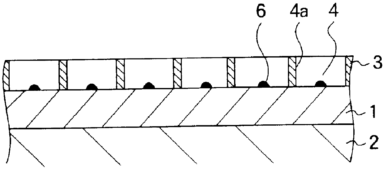
After irradiating the Ar ion beam, the surface of the carbon film was subjected to TEM observation. It was found that a plurality of Au ultrafine particles were formed on the carbon film at respective positions correspond...
embodiment 3
A carbon film was used as the substrate, and an Si mesh (a thickness of 300 .mu.m) having a large number of pores with a diameter of 150 .mu.m was placed as the target material on the carbon film. This Si mesh had the pores formed by etching with hydrofluoric acid. A Cu mesh as the supporting member on which the above laminate was positioned was placed on a room temperature stage in a vacuum chamber.
An Ar ion beam was irradiated in a slanting direction to the pores' inner walls of the Si mesh for 300 seconds while the carbon film and the Si mesh were being rotated at 2 rpm. The Ar ion beam had an acceleration voltage of 3.5 kV and a beam current of 0.5 mA. The Ar ion beam was irradiated at an incidence angle .theta. of 40 degrees. And, the Ar ion beam was irradiated in a vacuum atmosphere (containing Ar) of about 1.times.10.sup.-3 Pa.
After irradiating the Ar ion beam, the surface of the carbon film was subjected to TEM observation. It was found that a plurality of Si ultrafine parti...
embodiment 4
The Pt ultrafine particles (a large number of Pt ultrafine particles 32 shown in FIG. 6) produced in Embodiment 1 were used to prepare ultrafine particle bonded bodies. First, an electron beam of 1.0.times.10.sup.20 e / cm.sup.2 .multidot.sec was irradiated to the great number of Pt ultrafine particles for 240 seconds. FIG. 10 shows the electron diffraction pattern at the time.
FIG. 11 shows schematically a result of TEM observation after irradiating the electron beam for 700 seconds. It is seen from FIG. 11 that the Pt ultrafine particles 32 were mutually bonded by the irradiation of the electron beam to produce Pt ultrafine particle bonded bodies 33. FIG. 12 shows schematically an HETRM image of the area enclosed by a dash and dotted line in FIG. 11. It is seen from FIG. 12 that by irradiating an electron beam of 1.0.times.10.sup.20 e / cm.sup.2 .multidot.sec to the plurality of Pt ultrafine particles disposed to adjoin mutually for 700 seconds, there were obtained respective Pt ultraf...
PUM
| Property | Measurement | Unit |
|---|---|---|
| Diameter | aaaaa | aaaaa |
| Size | aaaaa | aaaaa |
| Energy | aaaaa | aaaaa |
Abstract
Description
Claims
Application Information