Solid microlaser passively switched by a saturable absorber and its production process

Inactive Publication Date: 2000-02-08
COMMISSARIAT A LENERGIE ATOMIQUE ET AUX ENERGIES ALTERNATIVES
View PDF13 Cites 52 Cited by
  • Summary
  • Abstract
  • Description
  • Claims
  • Application Information

AI Technical Summary

Problems solved by technology

However, this requires adapted electronics and makes the laser system more complicated.
This charge compensation problem is made all the more difficult to solve in that the crystals described in the article by M. B. Carmago et al are firstly produced in soli

Method used


Image

  • Solid microlaser passively switched by a saturable absorber and its production process
  • Solid microlaser passively switched by a saturable absorber and its production process
  • Solid microlaser passively switched by a saturable absorber and its production process

Examples


performance example

A LMA:Co crystal was produced and doped with 0.3% of Co.sup.2+ cobalt ions, which amounts to substituting for the Mg.sup.2+ ion in the formula of LMA (La.sub.0.9 Mg.sub.0.5 Al.sub.11.433 O.sub.19). With cobalt doping said formula becomes La.sub.0.9 Mg.sub.0.4985 Co.sub.0.0015 Al.sub.11.433 O.sub.19.

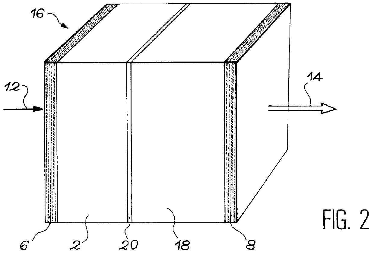
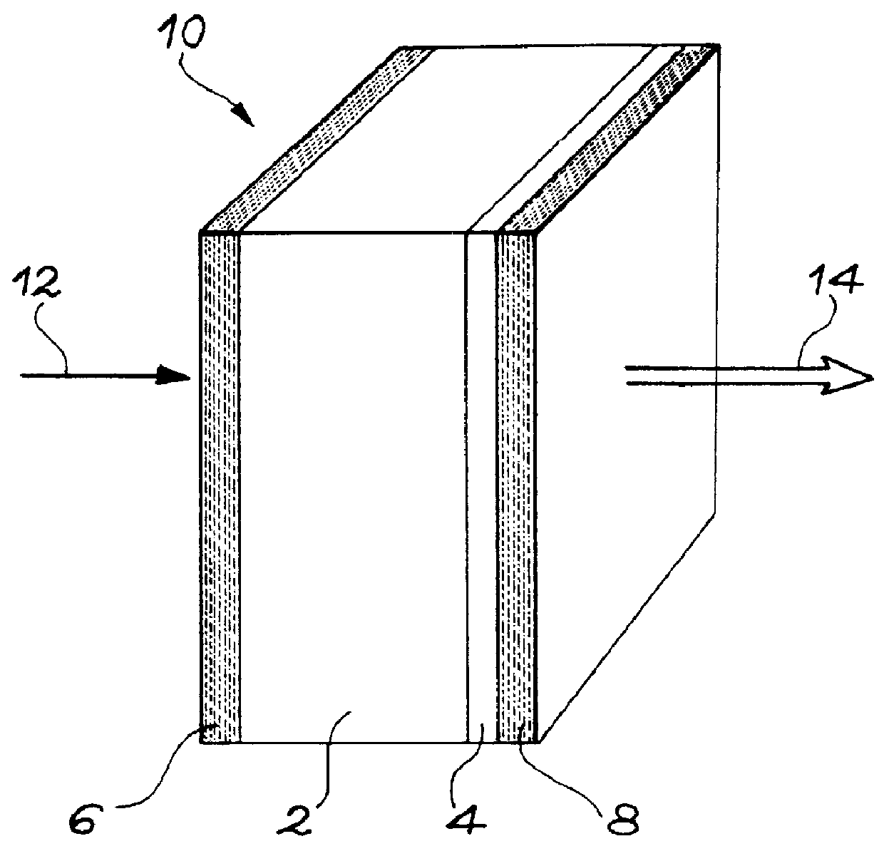
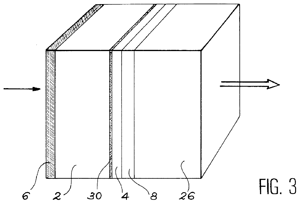
The crystal is oriented . This crystal was cut into small lamellas of diameter 5 mm. Different thicknesses were produced: 500, 750 and 1000 .mu.m. The two faces of the lamellas are polished, so as to obtain two faces which are as planar and parallel as possible. These lamellas are mechanically assembled with a Yb--Er-doped glass lamella, which is the laser material, and two mirrors forming the laser cavity. The mirrors are produced by a multilayer dielectric treatment. They are designed to operate at 1.5 .mu.m, which is the wavelength used here. The glass:Er, Yb used is a material bought from Kigre, U.S.A. It has the following Er and Yb composition: 0.6 to 0.8 wt. % erbium oxide and 20 wt...


PUM


Abstract

The invention relates to a microlaser cavity (10) having: a solid active medium (2) emitting at least in a wavelength range between 1.5 and 1.6 mu m, and a saturable absorber (4) of formula CaF2:Co2+ or MgF2:Co2+ or SrF2:Co2+ or BaF2:Co2+ or La0.9Mg0.5-xCoxAl11.433O19 or YAlO3:Co2+ (or YAl5-2xCoxSixO3) or Y3Al5-x-yGaxScyO12:Co2+ (or -3Al5-x-y2zGaxScyCozSizO12) or Y3-xLuxAl5O12Co2+ (or Y3-xLuxAl5-2yCoySiyO3) or Sr1-xMgxLayAl12-yO12:Co2+ (or Sr1-xMgx-yCoyLazAl12-zO12, with o<y<x).

Description

TECHNICAL FIELD AND PRIOR ARTThe present invention relates to a solid microlaser, a cavity for said microlaser and a process for the production of said cavity.One of the advantages of the microlaser is its structure in the form of a stack of multilayers. The active laser medium is constituted by a material of limited thickness between 150 and 1000 .mu.m and small dimensions (a few mm.sup.2), on which are directly deposited dielectric cavity mirrors. This active medium can be pumped by a III-V laser diode, which is either directly hybridized on the microlaser, or coupled to the latter by an optical fibre. The possibility of collective production using microelectronic means allows a mass production of such microlasers at very low cost.Microlasers have numerous applications in fields as varied as the car industry, the environment, scientific instrumentation and telemetry.Known microlasers generally have a continuous emission of a few dozen mW power. However, most of the aforementioned ...

Claims


Application Information

Patent Timeline
IPC IPC(8): H01S3/113H01S3/11H01S3/06H01S3/16
CPCH01S3/0627H01S3/113H01S3/0604
Inventor THONY, PHILIPPEMOLVA, ENGINFERRAND, BERNARDBOREL, CORINNE
Owner COMMISSARIAT A LENERGIE ATOMIQUE ET AUX ENERGIES ALTERNATIVES
Why Eureka
Try Eureka