Flat fluorescent lamp with specific electrode structuring

a fluorescent lamp and specific electrode technology, applied in the direction of discharge tube luminescnet screen, instruments, lighting and heating equipment, etc., can solve the problems of non-uniform discharge structure, sharp drop in surface luminous density towards the edge, temporally and spatially non-uniform surface luminous density,

Inactive Publication Date: 2000-03-07
PATENT TREUHAND GESELLSCHAFT FUR ELECTRIC GLUEHLAMPEN MBH
View PDF19 Cites 117 Cited by
  • Summary
  • Abstract
  • Description
  • Claims
  • Application Information

AI Technical Summary

Benefits of technology

It is possible by means of this concept to produce the three said functionally differing parts--internal electrodes, feedthroughs and external supply leads--as it were, simultaneously in a common production step, preferably by means of printing technology. By contrast with the prior art, the number of steps of manipulation and production is thereby greatly reduced. Furthermore, connections by means of soldering or the like between the individual components are eliminated.
Furthermore, the two structures offer the advantage of being able to be shaped in a virtually arbitrary fashion. As a result, the shapes of the electrodes which are optimized for a uniform surface luminous density up to the edges can be realized in a simple and cost-effective way in terms of production engineering. For example, only a structured printing screen need be appropriately configured for this purpose. A further advantage of the invention is that the design concept permits the cost-effective production of flat fluorescent lamps of virtually any size, since all the production steps can always be realized in the same way virtually independently of the size of the radiator. Consequently, suitable flat lamps for background lighting of liquid crystal displays of different sizes can be realized economically. Further advantages are the high luminous density and the high light yield, a typical specific light intensity being approximately 8 cd / W for a lamp including an optical diffuser. A range of further advantages of the flat lamps in conjunction with the pulsed mode of operation is set forth below. Since dielectrically impeded discharges operated in a pulsed fashion have a positive current-voltage characteristic, it is possible to arrange an arbitrary number of individual discharges next to one another, so that flat lamps of virtually any size can be realized in principle. Moreover, these flat lamps can be operated using only one electric ballast. Since the filling of the lamp contains no mercury, a threat due to poisonous mercury vapours is excluded and the problem of disposal is eliminated. A further advantage of the mercury-free filling is the instant start of the lamp without a starting performance. Because of the layer-like electrode structure without filigree individual parts, the lamp is, in addition, extremely robust and has a long service life.
In this case, a sufficiently high current carrying capacity of the conductor tracks requires a particular importance since the high luminous intensities aimed at for such flat lamps finally require high current intensities. To be precise, in the case of flat fluorescent lamps for background lighting of liquid crystal displays (LCD), a particularly high luminous intensity is mandatory because of the low transmission of such displays of typically 6%. This problem is further heightened in the case of the preferred pulsed mode of operation of the discharge, since particularly high currents flow in the conductor tracks during the relatively short duration of the repetitive injection of effective power. It is only in this way that it is also possible to inject sufficiently high average effective powers and thereby to achieve the desired high luminous intensity on average over time.
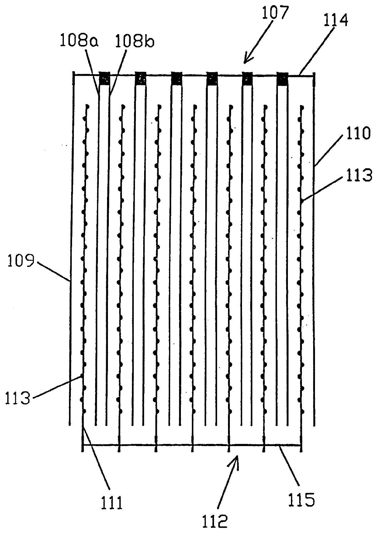
It is possible that a contribution is also made to this by support points specifically arranged at a suitable spacing from one another between the base plate and top plate, for example in the form of glass balls which lend the flat radiator sufficient bending stability without causing unacceptably strong shading.
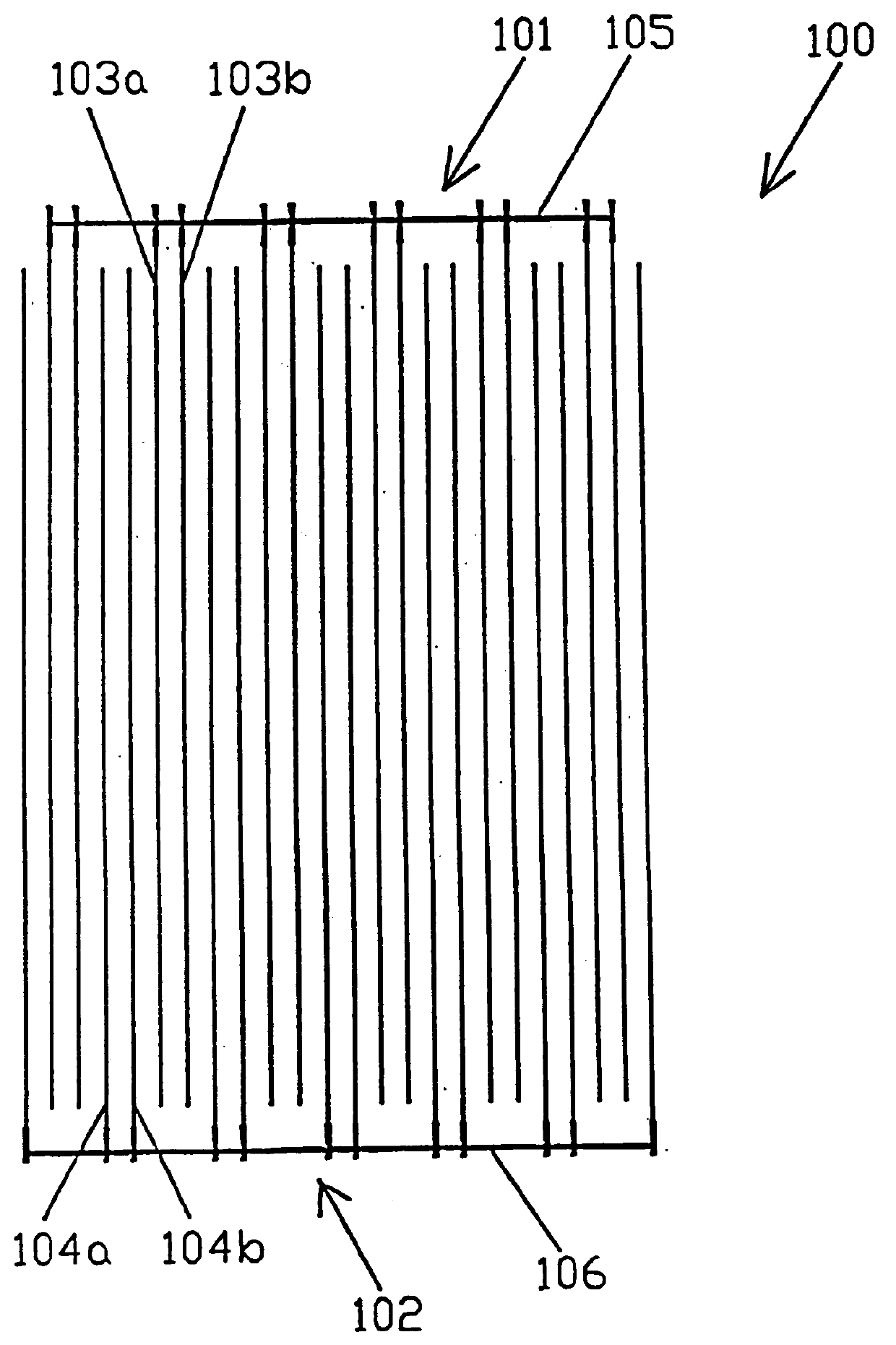
mIn a first embodiment, the strip-like electrodes are arranged next to one another on the base plate (Case I). This produces in operation an essentially plane-like discharge structure. The advantage is that shadows owing to the electrodes on the shining top plate are avoided. Instead of a single anode strip, as previously, two mutually parallel anode strips, that is to say an anode pair, are arranged in each case between the cathode strips. The result of this is to eliminate the problem outlined at the beginning that, in the quoted prior art, in each case only individual discharges of one of two neighbouring cathode strips burn in the direction of the individual anode strips situated therebetween.

Problems solved by technology

A further disadvantage of this solution is that the surface luminous density drops sharply towards the edge.
Referring to the flat radiator as a whole, this results in a non-uniform discharge structure, and consequently in a temporally and spatially non-uniform surface luminous density.
However, there are no data concerning the electrical feedthroughs for connecting the internal electrodes to a voltage source.
The disadvantage of this solution is that it is not possible to dispense with an optical conductor plate.
Nevertheless, unavoidable launching and scattering losses which reduce the achievable surface luminous density are produced in the redistribution from the linear light source (tubular fluorescent lamp) into the flat light source (optical conductor plate).
Moreover, the service life of the surface lighting unit is limited by the fluorescent lamps.
In the case of the use of a plurality of fluorescent lamps, the vulnerability of the entire unit grows increasingly.
Further disadvantages in the case of fluorescent lamps based on mercury low-pressure discharges result from the properties of the mercury itself.
Firstly, the mercury must first reach its operating vapour pressure, that is to say such fluorescent lamps exhibit a pronounced starting performance, something which makes it look rather inadvisable to turn off a PC monitor equipped therewith during a work break.
Moreover, mercury is injurious to health and must therefore be disposed of as hazardous waste.

Method used


Image

  • Flat fluorescent lamp with specific electrode structuring
  • Flat fluorescent lamp with specific electrode structuring
  • Flat fluorescent lamp with specific electrode structuring

Examples


Embodiment Construction

It is an object of the present invention to provide a flat fluorescent lamp with strip-like internal electrodes which has an electrode structure and electrical feedthroughs in such a way that the flat radiator--largely independently of the size and thus of the number of electrodes--can be produced in relatively few production steps and thus cost-effectively. A further aspect is the configuration, which is simple in terms of production engineering, of the electrode structures, which renders it possible to realize flat fluorescent lamps having an increased and uniform surface luminous density in a cost-effective fashion.

The basic idea of the first part of the invention consists in constructing the internal electrodes including the feedthroughs and external supply leads as three functionally different sections of in each case a single continuous cathode-side or anode-side structure resembling a conductor track.

It is possible by means of this concept to produce the three said functional...


PUM

PropertyMeasurementUnit
thicknessaaaaaaaaaa
thicknessaaaaaaaaaa
thicknessaaaaaaaaaa

Abstract

PCT No. PCT / DE98 / 00827 Sec. 371 Date Nov. 17, 1998 Sec. 102(e) Date Nov. 17, 1998 PCT Filed Mar. 20, 1998 PCT Pub. No. WO98 / 43277 PCT Pub. Date Oct. 1, 1998A flat fluorescent lamp (1) has a discharge vessel (2) having a base plate (7), a top plate (8) and a frame (9) which are connected to one another in a gas-tight fashion by means of solder (10). Structures resembling conductor tracks function in the interior of the discharge vessel as electrodes (3-6), in the feedthrough region as feedthroughs, and in the external region as external supply leads (13; 14). Flat lamps of the most different sizes can thereby be produced simply in engineering terms and in a fashion capable of effective automation. Moreover, virtually any electrode shapes can be realized, in particular optimized with regard to a uniform luminous density with a reduced drop in luminous density towards the edges of the flat lamp. At least the anodes (5, 6) are covered in each case with a dielectric layer (15). The lamp (1) is preferably operated by means of a pulsed voltage source and serves as background lighting for LCDs, for example in monitors or driver information displays.

Description

The invention relates to a flat fluorescent lamp for background lighting. Moreover, the invention relates to a lighting system and having this flat fluorescent lamp. Furthermore, the invention relates to a liquid crystal display device and having this lighting system.The designation "flat fluorescent lamp" is understood here to mean fluorescent lamps having a flat geometry and which emit white light. They are first and foremost designed for background lighting of liquid crystal displays, also known as LCDs.Also at issue here are flat lamps having strip-like electrodes, in which either the electrodes of one polarity or all the electrodes, that is to say of both polarities, are separated from the discharge by means of a dielectric layer (discharge dielectrically impeded at one end or two ends). Such electrodes are also designated as "dielectric electrodes" below for short.The term "strip-like electrode" or "electrode strip" for short is to be understood here and below as an elongated ...

Claims


Application Information

Patent Timeline
Patent Type & Authority Patents(United States)
IPC IPC(8): H01J65/04H01J61/30H01J61/92H01J61/00F21V7/00G02F1/13357G02F1/1335H01J61/067H01J65/00
CPCH01J61/305H01J61/92H01J65/046H01J61/00
Inventor VOLLKOMMER, FRANKHITZSCHKE, LOTHAR
Owner PATENT TREUHAND GESELLSCHAFT FUR ELECTRIC GLUEHLAMPEN MBH
Why Eureka
Try Eureka