Circuit arrangement for measuring an ion current in a combustion chamber of an internal combustion engine

Inactive Publication Date: 2000-03-28
VOLKSWAGEN AG +1
View PDF13 Cites 16 Cited by
  • Summary
  • Abstract
  • Description
  • Claims
  • Application Information

AI Technical Summary

Benefits of technology

In connection with a multi-cylinder internal combustion engine it is possible to connect the secondary windings and thus the spark plugs which function as ion current probes or sensors in parallel to each other, thereby providing the advantage that the same diverting circuit branches can be used for all spark plugs. However, where for highly accurate measurements it is desirable to measure each ignition path and thus each spark plug separately with regard to the ion current flow, each spark plug ignition circuit may be provided with a circuit arrangement according to the invention to thereby measure each spark plug independently of any other spark plug. In such a circuit arrangement the output signals would be time multi-plexed for evaluation.
According to an especially preferred embodiment of the invention each secondary winding of the ignition system for a multi-cylinder engine is

Problems solved by technology

The circuit arrangement of the above mentioned U.S. Patent is not cost efficient since it requires two inverting differential amp

Method used


Image

  • Circuit arrangement for measuring an ion current in a combustion chamber of an internal combustion engine
  • Circuit arrangement for measuring an ion current in a combustion chamber of an internal combustion engine

Examples


Embodiment Construction

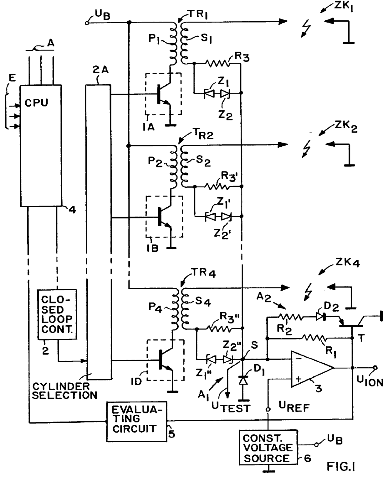
FIG. 1 shows a transistor ignition circuit for a four cylinder internal combustion engine. Each cylinder has its own spark plug Zk.sub.1 . . . Zk.sub.4. Further, each cylinder has its own ignition coil or transformer Tr.sub.1 . . . Tr.sub.4. Each ignition transformer has a primary winding P.sub.1 . . . P.sub.4 and a secondary winding S.sub.1 . . . S.sub.4. The spark plugs Zk.sub.1 . . . Zk.sub.4 are connected between the high voltage end of the respective secondary winding S.sub.1 . . . S.sub.4 and ground. One end of the primary windings is connected to a common supply battery U.sub.B. The other end of the primary windings is connected to a respective power amplifier or switch 1A, 1B, 1C, and 1D. These power switches are transistor amplifiers connected with their control electrodes to a timing circuit 2A which in turn is connected to a closed loop control circuit 2 having an input connected to a central processing unit 4. The battery U.sub.B provides a voltage for example of 12 V. T...


PUM


Abstract

A circuit arrangement measures an ion current generated in the combustion chamber of an internal combustion engine during an iron current flow phase following an ignition phase. A voltage drop across a feedback resistor (R1) connected in parallel to an inverting amplifier is measured since the voltage drop is proportional to the ion current resistance. The amplifier is connected with its inverting input to a low voltage end of a secondary winding of an ignition transformer or coil. The high voltage end of the secondary winding is connected through a spark gap of a spark plug to ground, whereby the spark plug functions as an ion current sensor during the ion current flow phase. Negative voltage peaks flowing during an ignition phase and the ignition current flowing during the ignition phase are diverted through respective first and second circuit branches. The first branch has a first semiconductor diode (D1) grounding the low voltage end of the secondary winding for discharging the negative high voltage peaks while blocking the ignition current. The other diverting branch has a second semiconductor (D2) connected in parallel to the inverting amplifier.

Description

INCORPORATION BY REFERENCEThe disclosure of German parent case No. 196 05 803.1, filed on Feb. 16, 1996 is hereby incorporated by reference into the present disclosure.The invention relates to a circuit arrangement for measuring an ion current occurring in a combustion chamber of an internal combustion engine after the flow of an ignition current, when an ignition spark has been extinguished, and prior to the next sparking or ignition phase.BACKGROUND INFORMATIONU.S. Pat. No. 5,483,818 discloses an ion measuring circuit of the type described above. The known circuit comprises an inverting amplifier wired as a differential amplifier, the inverting input of which is connected through a resistor to the low voltage potential side of the secondary winding of an ignition coil also referred to as an ignition transformer having a primary winding and a secondary winding. The differential amplifier has a further non-inverting input connected to a biasing voltage of about 40 V. The inverting a...

Claims


Application Information

Patent Timeline
IPC IPC(8): F02P15/10F02P15/00F02P3/02F02P17/12F02P3/045
CPCF02P3/0456F02P15/10F02P17/12F02P2017/125
Inventor BAHR, ULRICHDAETZ, MICHAEL
Owner VOLKSWAGEN AG
Why Eureka
Try Eureka