Protection circuit for use during burn-in testing

a protection circuit and burn-in testing technology, applied in pulse manipulation, pulse technique, instruments, etc., can solve the problems of reducing system capability, and reducing system performance in both battery and non-battery operated systems. , to achieve the effect of preventing damage caused by over-voltage, avoiding over-voltage damage, and not affecting the efficiency of the charge pump 300

Inactive Publication Date: 2000-05-02
ROUND ROCK RES LLC
View PDF43 Cites 7 Cited by
  • Summary
  • Abstract
  • Description
  • Claims
  • Application Information

AI Technical Summary

Benefits of technology

During normal operation, the BURNIN.sub.-- P signal is LOW (having a value lower than V.sub.CC) and the switching transistor 360 is off, removing the protection circuit PC1 from the system so as not to affect the efficiency of the charge pump 300. During burn-in testing conditions, the BURNIN.sub.-- P signal steps up to a value (V.sub.CCP) higher than V.sub.CC, causing switching transistor 360 to go into pinch-off mode, and allowing current (I.sub.ds) to flow from the drain terminal 364 to the source terminal 362. Once I.sub.ds >0 the voltage clamp 370 becomes part of the system and clamps down the voltage of the high-voltage node to V.sub.CC +V.sub.tswitch +V.sub.t1 + . . . +V.sub.tn (where n is the number of diode-connected transistors and V.sub.tx is the voltage drop across each transistor) thus avoiding over-voltage damage.
Protective circuits PC2, PC3, and PC4 are similar to protective circuit PC1 and include a switching transistor and a voltage clamp. The number and the value of diode-connected transistors in each voltage clamp varies according to the expected over-voltage values of the high-voltage node and the desired clamping voltage. Protection circuits allow accurate burn-in testing of a variety of charge pump designs or of any other IC device having high-voltage nodes at risk of over-voltage damage, while preventing damage caused by over-voltages. The protection circuit can be manufactured as part of the IC device, thereby avoiding the need to add additional components or assembly steps. Finally, protection circuits do not affect the efficiency of the IC device during normal operation.

Problems solved by technology

Inefficiencies in conventional charge pumps lead to reduced system capability and lower system performance in both battery and non-battery operated systems.
Inefficiency can adversely affect system capabilities causing limited battery life, excess heat generation, and high operating costs.
Examples of lower system performance include low speed operation, excessive delays in operation, loss of data, limited communication range, and the inability to operate over wide variations in ambient conditions including ambient light level and temperature.
"Infant mortality" is the failure of an integrated circuit (IC) early in its life due to manufacturing defects.
Limited reliability of a charge pump can affect the reliability of the entire system.
Low frequency components cause interference between portions of a system, intermittent failures, and reduced system reliability.
Elevated frequency operation in some cases leads to increased system power dissipation with attendant adverse effects.
When an IC charge pump is tested during a burn-in cycle, high burn-in over-voltages in combination with high burn-in temperatures can cause oxidation of silicon layers of the IC device and can permanently damage the charge pump.

Method used


Image

  • Protection circuit for use during burn-in testing
  • Protection circuit for use during burn-in testing
  • Protection circuit for use during burn-in testing

Examples


Embodiment Construction

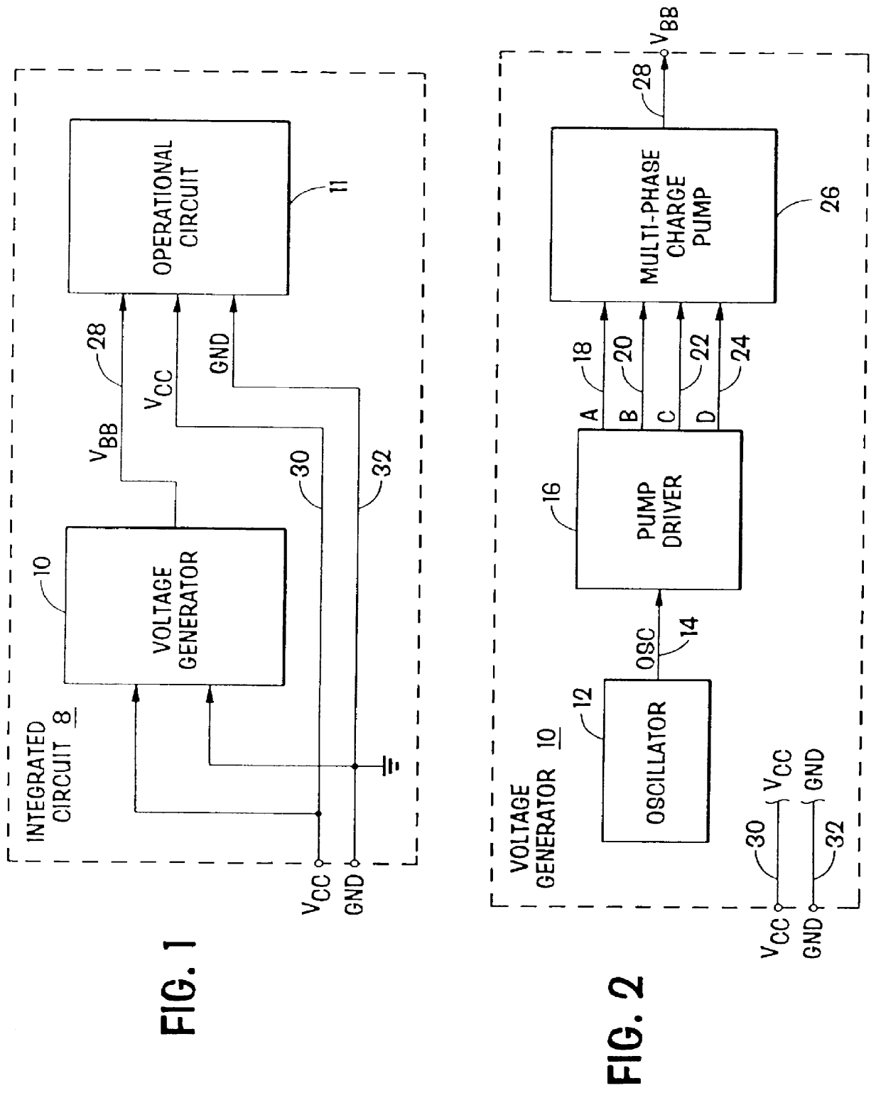
FIG. 1 is a functional block diagram of an integrated circuit of the present invention. Integrated circuit 8 includes voltage generator 10 and operational circuit 11 formed on a substrate. Integrated circuit a receives power signal V.sub.CC on line 30 and a ground reference signal GND on line 32. A DC voltage therebetween provides operating current to voltage generator 10 and operational circuit 11, thereby powering integrated circuit 8.

Power supplied to integrated circuit 8 is converted by voltage generator 10 to an intermediate voltage V.sub.BB. The voltage signal V.sub.BB has a magnitude outside the range from GND to V.sub.CC, For example, when the voltage of signal V.sub.CC is 3.3 volts referenced to GND, the voltage of signal V.sub.BB in one embodiment is about -1.5 volts and in another embodiment is about -5.0 volts. Voltages of opposite polarity are used as substrate bias voltages for biasing the substrate in one embodiment wherein integrated circuit 8 is fabricated with a MO...


PUM


Abstract

A multi-phase charge pump continuously pumps to establish a DC voltage outside the range of supply and reference voltages. The multi-phase charge pump in one embodiment includes four stages operating in a ring with a four-phase clock. Each stage includes a three-mode charge pump that generates and provides reset and control signals to other stages. Each stage includes a pass transistor having a gate driven in excess of the DC voltage for efficient transfer of charge. The gate drive signal from a first stage is coupled to a next stage in the ring where it is used to generate the next gate drive signal. Each gate drive signal corresponds to one waveform having a phase skewed in time so that each stage in the ring is operating in a different mode. In a method of use, a first stepped voltage is developed on a first capacitor and selectively coupled to a second capacitor to develop a second stepped voltage of greater absolute value. The second stepped voltage gates charge transfer from a first stage and enables the selective coupling in a next stage in a sequence of pump stages. The pump stages include protection circuits protecting high-voltage nodes during burn-in testing. The charge pump includes a burn-in detector circuit for detecting burn-in conditions and for turning on the protection circuits and a pump regulator for regulating the output of the charge pump.

Description

1. Field of the InventionThis invention relates to supplying power to a circuit and particularly to systems including pumped power supplies.2. Description of Related ArtSystem designs are routinely constrained by a limited number of power supply voltages (V.sub.CC). For example, consider a portable computer system powered by a conventional battery having a limited power supply voltage. For proper operation, different components of the system, such as a display, a processor, and memory employ several technologies which require power to be supplied at various operating voltages. Components often require operating voltages of a greater magnitude than the power supply voltage or in other cases involve a voltage of reverse polarity. The design of a system, therefore, includes power conversion circuitry to efficiently develop the required operating voltages. One such power conversion circuit is known as a charge pump.The demand for highly-efficient and reliable charge pump circuits has in...

Claims


Application Information

Patent Timeline
Patent Type & Authority Patents(United States)
IPC IPC(8): H03K5/08G05F3/24H02M3/07
CPCG05F3/24H02M3/073G05F3/242
Inventor MANNING, TROY
Owner ROUND ROCK RES LLC
Why Eureka
Try Eureka