Receiver for a navigation system, in particular a satellite navigation system

a satellite navigation and receiver technology, applied in the direction of navigation instruments, transmission, instruments, etc., can solve the problems of increasing the random noise level, affecting the accuracy of satellite navigation, so as to simplify the loop filter

Inactive Publication Date: 2000-05-30
EUROPEAN SPACE AGENCY
View PDF6 Cites 162 Cited by
  • Summary
  • Abstract
  • Description
  • Claims
  • Application Information

AI Technical Summary

Benefits of technology

As a result, the phase measurements performed in the second processor are used to reduce the dynamic range of the signals to be processed by the first processor, thereby making it possible, in...

Problems solved by technology

However, given that the signals must pass through different analog devices, unknown bias necessarily arises.
This eliminates the effects of bias, but considerably increases random noise level.
Each of those architectures thus presents drawbacks in terms of results obtained, or in terms of implementation, and these are discussed below.
If independent reference signals were used, then it would not be possible to perform accurate differential carrier phase measurements, and it would be very difficult to separate real carrier phase differences from the phase drift of each reference signal.
A parallel architecture receiver has two main drawbacks, namely: hardware complexity; and bias due to propagation along the different lines of the various circuits.
Bias is the main cause of loss of accuracy.
Each device in the RF/IF chain presents finite group delay and thus gives rise to "line" bias, and in general line bias is not the same for all of the chains.
The RF filters and the IF filters contribute not only to the total group delay, but they are also very sensitive to temperature.
Although group propagation delays through the RF/IF paths of the different antennas can be matched to some extent and can also be calibrated, mismatching always arises because of temperature variations, ra...

Method used


Image

  • Receiver for a navigation system, in particular a satellite navigation system
  • Receiver for a navigation system, in particular a satellite navigation system
  • Receiver for a navigation system, in particular a satellite navigation system

Examples


Embodiment Construction

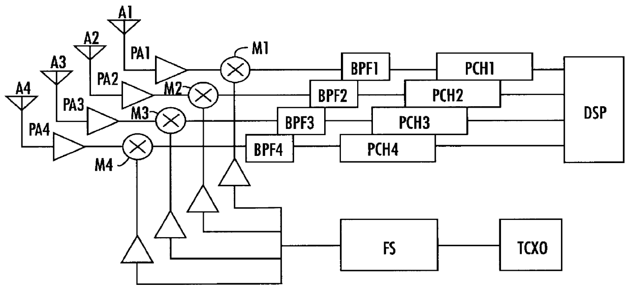
As shown in FIG. 1, a parallel architecture receiver has a plurality of antennas, e.g. four, referenced A.sub.1 to A.sub.4, feeding respective preamplifiers PA.sub.1 to PA.sub.4 whose outputs are applied to respective first inputs of mixers M.sub.1 to M.sub.4 whose other inputs receive signals delivered by a frequency synthesizer FS under the control of a stable crystal oscillator TCXO. The outputs from the mixers M.sub.1 to M.sub.4 are applied to respective bandpass filters BPF.sub.1 . . . BPF.sub.4 whose outputs are connected to processing channels PCH.sub.1 . . . PCH.sub.4 controlled by a digital signal processor DSP.

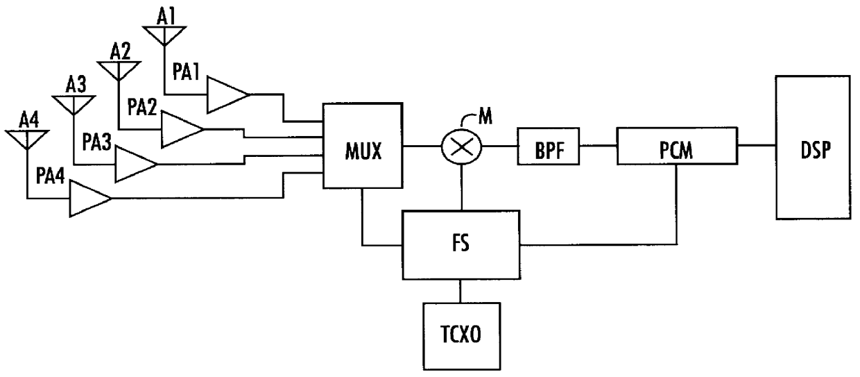
In FIG. 2, a multiplex receiver receives output signals from antennas A.sub.1 to A.sub.4 and applies them to preamplifiers PA.sub.1 to PA.sub.4 whose outputs are applied to a common multiplexer MUX controlled as is the mixer M by a synthesizer FS itself driven by a stabilized oscillator TCXO. In this case, the digital signal processor DSP operates in time-multiplexed...


PUM


Abstract

The invention relates to a navigation system receiver comprising at least two antennas, one of which is a "reference" antenna. A multiplexer multiplexes the signals from the antennas, and a first processor situated downstream from the multiplexer delivers at least one navigation parameter on the basis of the signals from the multiplexer. The receiver includes a second processor having an input receiving in continuous manner signals from the reference antenna to deliver at least one reference signal representative of a position parameter of the reference antenna. Processor means process the signals from the multiplexer while taking account of at least one said reference signal.

Description

The present invention relates to a receiver for a navigation system, in particular a satellite navigation system.Receivers are already known that enable the attitude or the pointing direction of a vehicle such as a satellite to be determined by using the signals transmitted by global navigation satellite systems (GNSS), such as the American global positioning system (GPS) and the Russian global orbiting navigation satellite system (GLONASS). Geostationary navigation overlay systems (GNOS) such as the European geostationary navigation overlay system (EGNOS) can also be used.Receivers are already known that enable the attitude of satellites to be determined from GNSS signals by differential phase measurements, e.g. from the article by V. W. Spinney "Applications of the global positioning system as an attitude reference for near earth uses", published by the Institute of Navigation, Warminster, Pa. USA, April 1976, or from the article by A. K. Brown et al. entitled "Interferometric att...

Claims


Application Information

Patent Timeline
IPC IPC(8): G01S1/00G01C21/00G01S19/25G01S5/02G01S19/31G01S19/44G01S19/46
CPCG01S19/29G01S19/32G01S19/53G01S19/36G01S19/33
Inventor SILVESTRIN, PIERLUIGIDALY, PETERWALSH, DAVIDAARDOOM, ERIC
Owner EUROPEAN SPACE AGENCY
Why Eureka
Try Eureka