Method and apparatus for directional measurement of subsurface electrical properties

Inactive Publication Date: 2000-08-08
SINCLAIR PAUL L
View PDF26 Cites 219 Cited by
  • Summary
  • Abstract
  • Description
  • Claims
  • Application Information

AI Technical Summary

Problems solved by technology

The magnetic properties, while valuable, are not commonly measured by these methods due to the difficulty of separating their effects from those of conductivity.
However, the problem of adapting the induction technique to measurement-while-drilling has been found to be difficult, due to the influence of the mass of conductive metal in a drill-collar, and there are no known true MWD induction tools (directional or not) in commercial operation at this time.
Unfortunately, this limits the depth of investigation to significantly less than what a true induction tool can achieve and does not provide sufficient depth to modify the path of the drill bit before it has penetrated the formation.
While there is a continuing need for an induction tool for use in MWD, there are no commercially acceptable tools or services of this type available at this time.
Unfortunately, the requirements for drill collars are much more severe than for drill pipe in terms of mechanical stresses (axial, torsional, and bending combined), and resistan

Method used


Image

  • Method and apparatus for directional measurement of subsurface electrical properties
  • Method and apparatus for directional measurement of subsurface electrical properties
  • Method and apparatus for directional measurement of subsurface electrical properties

Examples


Embodiment Construction

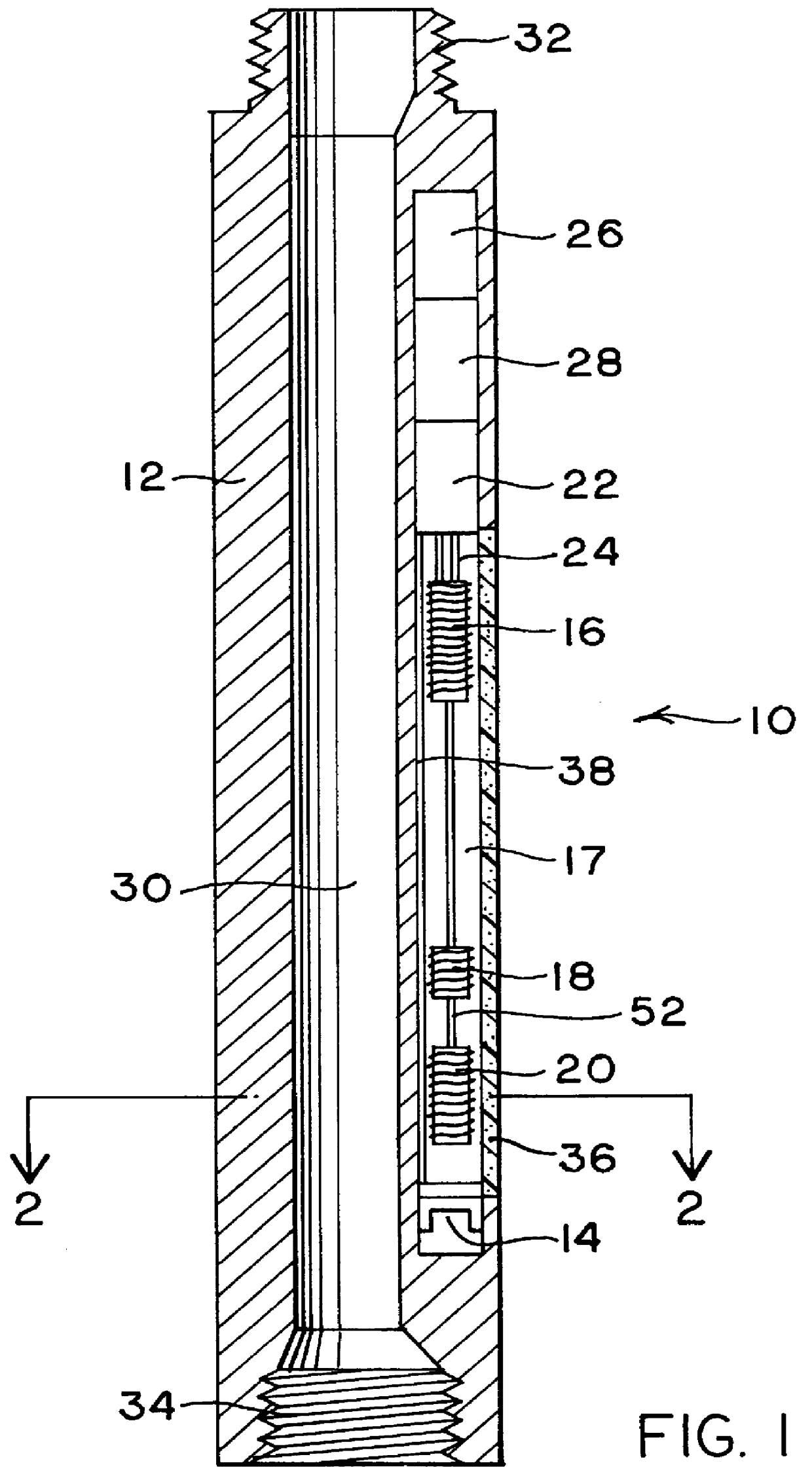
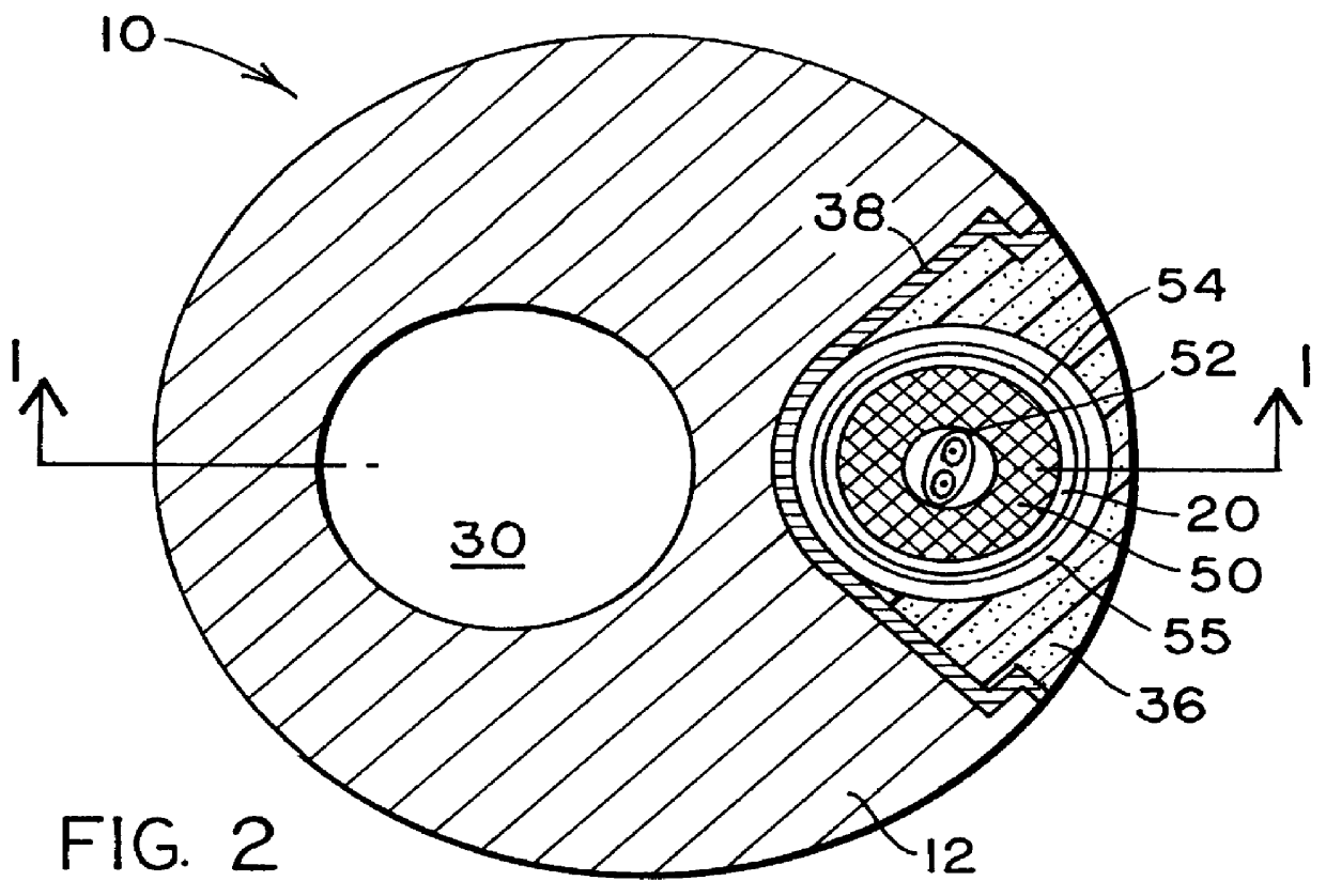
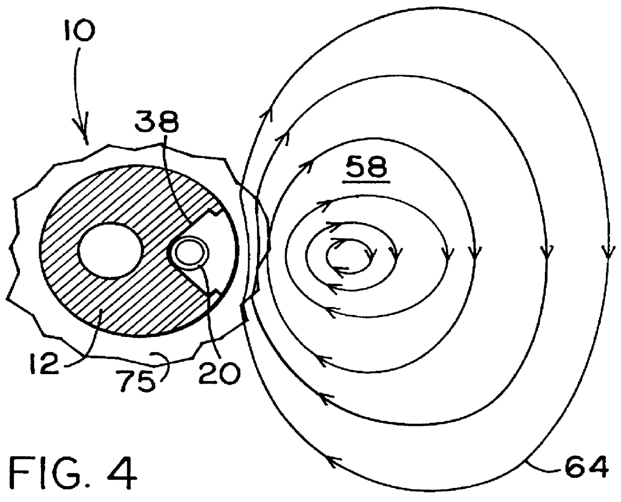
The basic physical theory underlying this invention is well-known in the study of electromagnetic fields. A solenoidal transmitter coil of wire that is energized with a timevarying (in preferred embodiments, sinusoidal) electric current will generate a proportionate time-varying magnetic field extending in all directions from the axis of the coil, such that in a proximate conductive medium circulating currents will be induced to flow. These are commonly known as Foucault or "eddy" currents, and their magnitude is proportional to the conductivity of the medium at distances from the coil much less than the skin-depth in the medium (defined as inversely proportional to the square-root of the product of frequency and conductivity). The Foucault currents in turn induce a proportionate voltage in other receiver coils placed in the vicinity, usually coaxially with the transmitter coil. In a true induction tool, the frequency is made low enough to substantially remove skin-effect, so that t...


PUM


Abstract

A directional induction logging tool is provided for measurement while drilling. This tool is preferably placed in a side pocket of a drill collar, and it comprises transmitter and receiver coils and an electromagnetic reflector. The reflector, which may be a layer of highly conductive material placed between the coils and the body of the drill collar, serves to focus the electromagnetic fields generated and sensed by the tool in the direction away from the reflector, thus providing a directional response to formation conductivity with a relatively high depth of investigation. In preferred embodiments of the invention, magnetically permeable cores are placed within the coils to concentrate the magnetic fields that pass through them. Circuitry is described for balancing the mutual inductive coupling of the coils by injecting a direct current signal through one or more of the coils, which alters the magnetic permeability of the core material. The magnitude of the direct current required to achieve a balanced condition may be derived from the quadrature phase component of the return signal. Circuitry is also provided for generating a transmitted signal and for processing the return signals, including digital-to-analog conversion circuitry for providing digital data for transmission to the surface. This tool may be employed to provide real-time directional conductivity information that may be used to detect and follow bed boundaries in geosteering operations.

Description

BACKGROUND OF TEE INVENTIONThe present invention relates to a logging tool used to search for underground mineral or fossil fuel deposits and, more particularly, to a method and apparatus for determining the electrical conductivity of formations proximate to a borehole.Electrical conductivity (or its inverse, resistivity) is an important property of a rock formation in geological surveys and prospecting for oil and gas because many minerals, and more particularly hydrocarbons, are less conductive than common sedimentary rocks. Thus a measure of the conductivity is often a guide to the presence and amount of oil or gas.Induction methods using coils to generate and sense time-varying electromagnetic fields are widely used in borehole geophysical surveys, or "logs", to determine the local rock properties including conductivity, dielectric permittivity, and magnetic permeability. Typically, arrays of such coils mounted coaxially with the borehole axis, and operating in the frequency ran...

Claims


Application Information

Patent Timeline
IPC IPC(8): G01V3/28G01V3/18
CPCG01V3/28
Inventor SINCLAIR, PAUL L.
Owner SINCLAIR PAUL L
Why Eureka
Try Eureka