Structures and methods of manufacture for gas diffusion electrodes and electrode components

Inactive Publication Date: 2000-08-15
IND DE NORA SPA
View PDF1 Cites 102 Cited by
  • Summary
  • Abstract
  • Description
  • Claims
  • Application Information

AI Technical Summary

Benefits of technology

We have changed the structure of the ELAT to accomodate the different reactant and product transport and electronic contact requirements of MEAs. FIG. 1 also shows a comparison of the standard ELAT structure to two embodiments of a new gas diffuser structure. In comparing diffuser type "A" of FIG. 1 to the standard ELAT, one notes both a reduction in the number of coated layers, which translates to less total deposited solids, and with coating layers being placed on only one side of the carbon cloth web. The uncoated side of the web is now oriented toward the gas feedstream while the coated layers are placed against the electrode (i.e, the face of the membrane electrode assembly). As will be shown in the Examples, these reduced layers and single-sided coatings allow for a reduced number of fabrication steps, and a thinner, more open structure amendable to high gas flux rates.
For diffuser type "A", there are still two or more types of carbon black employed in the architecture of the structure. These are selected so as to create a gradient of hydrophobicity throughout the structure, as well as to provide a layer that can be more easily wetted at the catalyst interface. However, there are applications where a single kind of carbon black is appropriate, and diffuser type "B" in FIG. 1 illustrates this alternative structure. For diffuser type "B", one or more coats of carbon black and binder are applied on one side of the web. This diffuser would be orientated as type "A", that is, the uncoated side is towards the feedgas plenum while the coated side is against the electrode face of the MEA. Diffuser type "B" is easier to fabricate, and is the least expensive to manufacture.
While much focus has been made on the structure and performance of gas diffusion electrodes, little contribution has been made in the nature and effect of carbon black preparation methods for gas diffusion electrodes. While the sonic horn is frequently cited, we show here surprising enhancements in diffuser and gas diffusion electrode performance through other dispersion methods. For example, one preferred method introduces a pressurized flowing stream of solvent and carbon black into a "Y" shaped chamber that divides the flow i

Problems solved by technology

However, the effectiveness of a mechanical method for intimately contacting the electrode to the polymer membrane electrolyte may be limited since the conducting membrane can frequently change dimensions with alterations in hydration and temperature.
This precipitation can be difficult to control due to the nature of the ion-conducting polymer membrane, the form of the metal salt, and the specific method employed to precipitate the metal.
Regardless, no information is relayed as to how this structure could be produced with economical means.
Thus, while the authors endorse the need for inexpensive manufacturing processes, they describe a batch coating design, which inherently limits product throughput.
Although suitable for limited production runs or R&D sized samples, there are several limitations to ultrasound.
Fi

Method used


Image

  • Structures and methods of manufacture for gas diffusion electrodes and electrode components
  • Structures and methods of manufacture for gas diffusion electrodes and electrode components
  • Structures and methods of manufacture for gas diffusion electrodes and electrode components

Examples


example 2

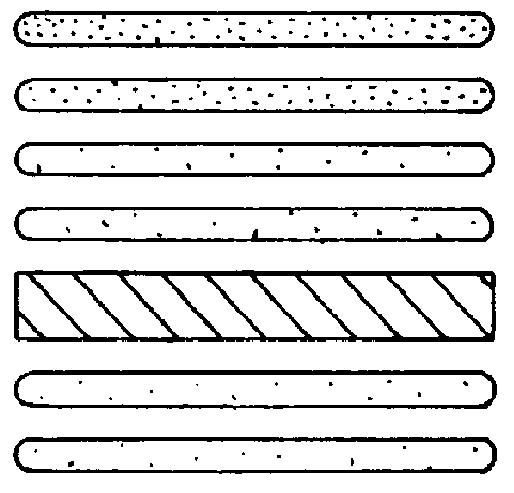
To construct a gas diffusion electrode or diffuser of type "A" structure of the invention, an identical procedure as outlined for Example 1 was followed, except the SAB / Teflon wetproofing layer was applied to one side of the web at approximately half the total carbon black loading, i.e. 1.5-3 mg / cm.sup.2. The catalyst coat and final treatment followed that as detailed above. To make a diffuser, similar steps were performed except uncatalyzed Vulcan XC 72 with a loading range of 0.5-1.5 mg / cm.sup.2 carbon black was employed.

example 3

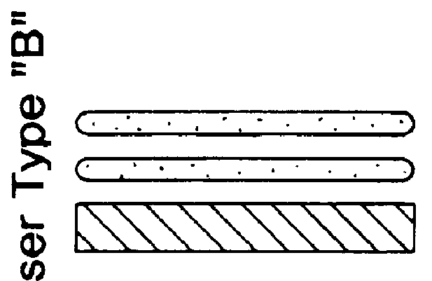
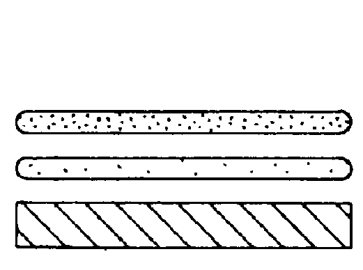
To construct a gas diffusion electrode or diffuser of type "B" structure of the invention, an identical procedure as outlined for Example 2 was followed However, only the SAB / Teflon wetproofing layer or platinum catalyzed Vulcan XC-72 was applied to one side of the web at at total loading of approximately 0.5-5 mg / cm.sup.2 Similar drying and heating steps as Example 1 followed. A diffuser was constructed in an identical manner except either SAB or Vulcan XC-72 without catalyst was employed.

example 4

A type "B" gas diffusion electrode similar to that of Example 3 was constructed through an automated coater. For this example, a knife-over-plate coater was used and the coater employed a 255 mm perpendicular stainless steel blade with a 45.degree. C. beveled edge. The blade was positioned over the cloth with a fixed gap of approximately 10 mils. The line speed was 2 meters / min., and mix, prepared as in Example 3, was fed at continuous rate to a reservoir in front of the blade. Samples thus prepared were subjected to the same heating and drying steps of Example 1.


PUM

PropertyMeasurementUnit
Linear densityaaaaaaaaaa
Angleaaaaaaaaaa
Thicknessaaaaaaaaaa

Abstract

Gas Diffusion Electrodes (GDES) play a pivotal role in clean energy production as well as in electrochemical processes and sensors. These gas-consuming electrodes are typically designed for liquid electrolyte systems such as phosphoric acid and alkaline fuel cells, and are commercially manufactured by hand or in a batch process. However, GDEs using the new electrolytes such as conductive polymer membranes demand improved electrode structures. This invention pertains to GDEs and gas diffusion media with new structures for systems using membrane electrode assemblies (MEAs), and automated methods of manufacture that lend themselves to continuous mass production Unexpected improvements in gas and vapor transport through the electrode are realized by incorporating a new dispersion process in the construction, reformulating the applied mix with solution additives, and creating a novel coating structure on a conductive web. Furthermore, combining these changes with a judicious choice in coating methodology allows one to produce these materials in a continuous, automated fashion.

Description

A gas diffusion electrode (GDE) consumes or is depolarized by a gas feed while allowing direct electronic transfer between the solid and gas phase. Together with the electrolyte, the GDE provides a path for ionic transfer, which is just as critical. GDEs are typically constructed from a conductive support, such as a metal mesh, carbon cloth, or carbon paper. This support is often called a web. The web is coated with hydrophobic wet-proofing layers, and finally, a catalytic layer is applied most commonly to one face. While the catalytic layer can consist of very fine particles of a precious metal mixed with a binder, many employ the methods similar to that in Petrow, et al., U.S. Pat. No. 4,082,699. This patent teaches the use of using finely divided carbon particles such as carbon black as the substrate for small (tens of angstroms) particles of the nobel metal. Thus called a "supported" catalyst, this methodology has shown superior performance and utilization of the catalyst in ele...

Claims


Application Information

Patent Timeline
IPC IPC(8): C25B11/00C25B11/03H01M4/88H01M4/96H01M8/10H01M8/02H01M4/92H01M4/90H01M4/86
CPCC25B11/035H01M4/8807H01M4/8828H01M4/886H01M4/8882H01M4/8885H01M4/926H01M4/96H01M8/0232H01M8/0234H01M8/0239H01M8/0243H01M8/0245H01M8/1004H01M4/8896H01M2300/0082Y02E60/522Y02P70/50Y02E60/50C25B11/031
Inventor DEMARINIS, MICHAELDE CASTRO, EMORY S.ALLEN, ROBERT J.SHAIKH, KHALEDA
Owner IND DE NORA SPA
Why Eureka
Try Eureka