Method for re-cycling wellbore cuttings

a wellbore and cutting technology, applied in the direction of filtration separation, borehole/well accessories, separation processes, etc., can solve the problems of increasing the wear of mud pumps and other mechanical equipment used for drilling, increasing the difficulty of cuttings on-site at offshore rigs, and increasing the cost of operation, so as to reduce the size of condensing and particulate collection equipment and high hydrocarbon contamination

Inactive Publication Date: 2000-08-22
TUBOSCOPE VETCO INT
View PDF38 Cites 101 Cited by
  • Summary
  • Abstract
  • Description
  • Claims
  • Application Information

AI Technical Summary

Benefits of technology

To effect vaporization of the water and hydrocarbons from the material while in the dryer, the material is heated to temperatures required to vaporize those water and hydrocarbon constituents. These temperatures are typically between 500.degree. F. and 900.degree. F. Material leaving the dryer is mixed with water for cooling and added moisture.
Either indirect or direct fired dryers may be used. The use of indirect dryer

Problems solved by technology

If drilled solids are not removed from the mud used during the drilling operation, recirculation of the drilled solids can create weight, viscosity, and gel problems in the mud, as well as increasing wear on mud pumps and other mechanical equipment used for drilling.
Remediation of cuttings on-site at an offshore rig is a di

Method used


Image

  • Method for re-cycling wellbore cuttings
  • Method for re-cycling wellbore cuttings
  • Method for re-cycling wellbore cuttings

Examples


Embodiment Construction

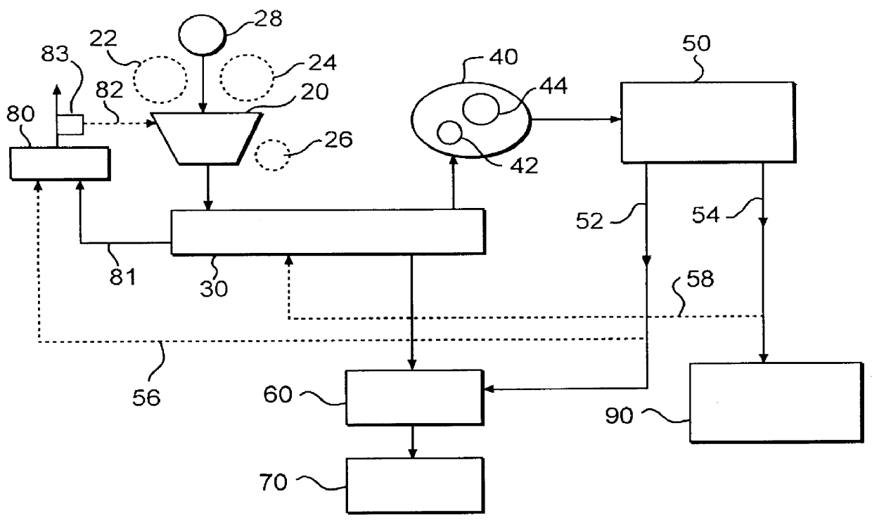
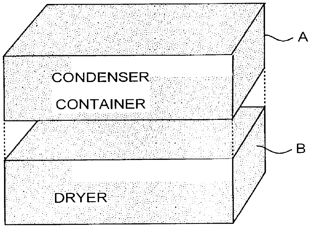
As shown in FIG. 1, one particular embodiment of a system 10 according to the present invention has a feed hopper 20; a dryer 30; a condenser 40; an oil / water separator 50; a rehydration system 60; a discharge 70; an exhaust stack 80; and an oil processor 90. In one particular aspect all of the major components are sized for containment in two containers which, when stacked, occupy a volume 81 / 2'.times.20'.times.20'. By using stackable containers the system's "footprint" on an offshore rig. where space is at a premium, is minimized. In one aspect the container weight is low enough for helicopter transport.

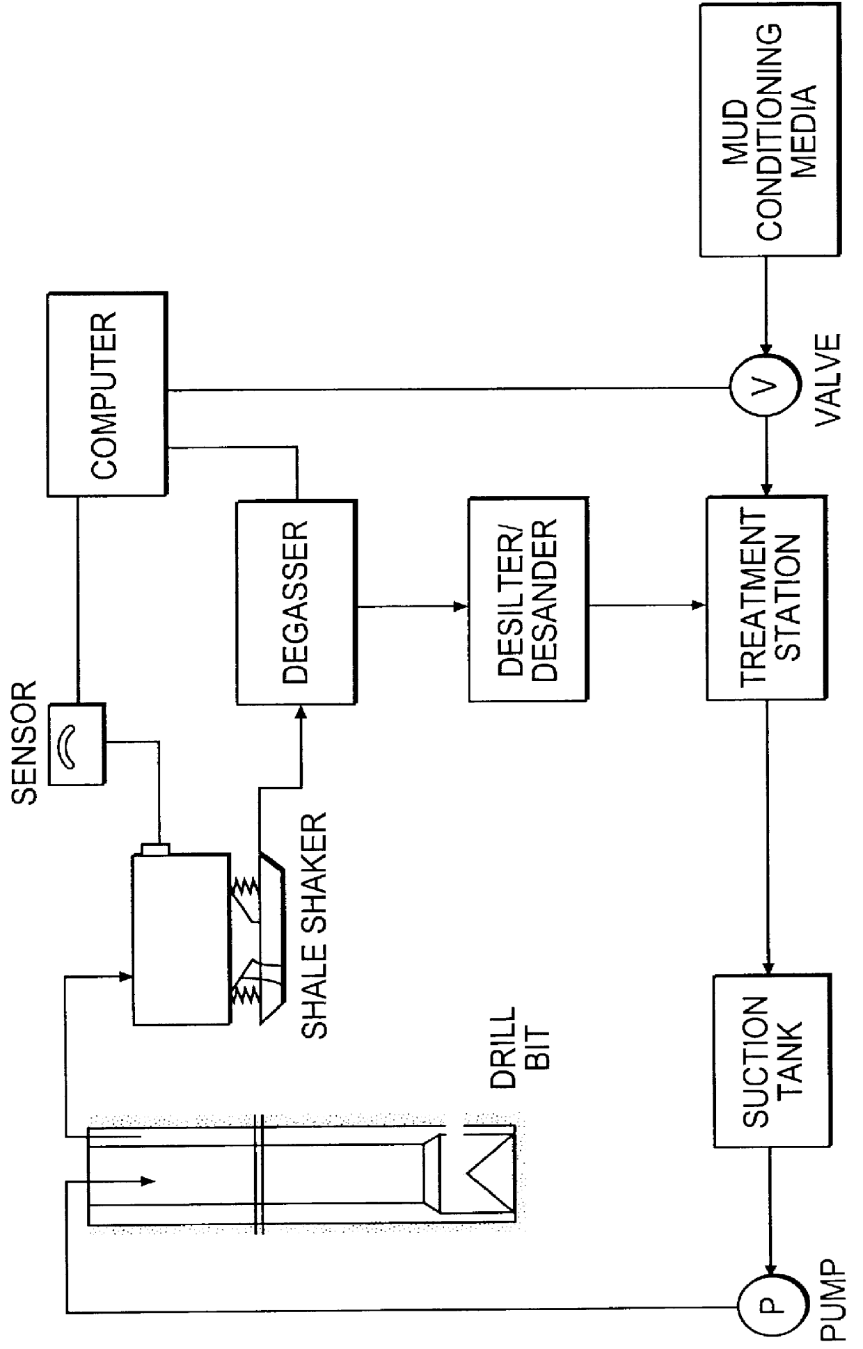
Initially, cuttings in a drilling fluid are processed by a rig's shaker system, producing fluid, soil, and oily contaminated cuttings and solids (collectively "oily solids"). These oily solids in a slurry of solids, oil and water are fed to the feed hopper 20 (e.g. from: an end loader; conveyor belt; auger; vacuum system from the shakers; mud cleaner, hydrocyclone and / or centrifuge...


PUM

PropertyMeasurementUnit
Fractionaaaaaaaaaa
Fractionaaaaaaaaaa
Fractionaaaaaaaaaa

Abstract

A method for remediating cuttings from a wellbore has been invented which, in certain aspects, includes transporting a system for remediating the cuttings to an offshore rig in transportable containers, the system including a thermal treatment system and a condensing system; feeding a slurry of the cuttings with oil and water to the thermal treatment system and heating the cuttings therein producing heated cuttings an a stream with oil and water; discharging the heated cuttings from the thermal treatment; feeding the stream with oil and water to a condenser system producing a liquid stream; and feeding the liquid stream to an oil/water separator producing an oil stream and a water stream. In another method for remediating cuttings according to the present invention, the method includes feeding a slurry of the cuttings with oil, fine particulates, and water to a thermal treatment system and heating the cuttings therein producing heated cuttings and a stream with oil and water, discharging the heated cuttings from the thermal treatment, feeding the stream with oil and water to the filter system, filtering out fine particulates from the stream with oil and water, feeding the stream with oil and water to a condenser system producing a liquid stream, and feeding the liquid stream to an oil/water separator producing an oil stream and a water stream.

Description

1. Field of the InventionThe present invention is directed to systems for treating and re-cycling wellbore drilling cuttings, and, in one aspect, to such systems for offshore drilling rigs.2. Description of Related ArtDrilling fluids used in hydrocarbon well drilling, as well known in the prior art, pick up solid cuttings and debris which must be removed if the fluid is to be re-used. Drilling fluid, called "mud," is typically either water based or oil-based. Typically a mud with various additives is pumped down through a hollow drill string (pipe, drill collar, bit, etc.) into a well being drilled and exits through holes in a drillbit. The mud picks up cuttings (rock), other solids, and various contaminants, such as, but not limited to, crude oil, water influx, salt and heavy metals from the well and carries them upwardly away from the bit and out of the well in a space between the well walls and the drill string. At the top of the well, the contaminated solids-laden mud is dischar...

Claims


Application Information

Patent Timeline
IPC IPC(8): E21B21/06E21B21/00
CPCB09B3/0091E21B21/066B09B3/45
Inventor WOOD, BRADFORD R.
Owner TUBOSCOPE VETCO INT
Why Eureka
Try Eureka