Charge-exchange device

a technology of discharge and discharge, which is applied in the direction of particle separator tubes, beam/ray deflecting arrangements, thermonuclear fusion reactors, etc., can solve the problems of difficult to take countermeasures, damage to the foil, and difficult to keep the foil in a sound condition

Inactive Publication Date: 2000-10-24
JAPAN ATOM ENERGY RES INST
View PDF1 Cites 5 Cited by
  • Summary
  • Abstract
  • Description
  • Claims
  • Application Information

AI Technical Summary

Benefits of technology

Ionization by light excitation method by use of an optical resonator is proposed for the ionizer. It can be said that presence of a wiggler magnetic field is effective for exciting the neutral atom in the ground state to one step higher level, which has mitigated the load over the laser considerably. The advantage of the beam of 1.5 GeV is used to the maximum extent and also use of the Lorentz force, application of the relativistic Doppler effect and so forth have largely contributed to ionization. It has been turned out that use of a wiggler magnetic field and photon has reduced the adverse affect such as scattering of the circulating ion and is extremely advantageous.
It is further to be understood that use of relativistic Doppler effect and an optical resonator mitigates the load over the laser output. By using the resonance excitation method to efficiently excite the neutral atom in the ground state to the level of n=3, the load over the laser is said to be mitigated. Since the absorption sectional area for the resonance excitation is largely dependent on the width distribution of the velocity of the H.sup.0 beam that has been accelerated, if the width distribution of the velocity of the H.sup.0 beam may be made smaller, the laser output may correspondingly be mitigated.

Problems solved by technology

In this instance, it should be noted that since the foil will be exposed to radiation by the particles themselves which have been injected for a long period of time and the proton beam which has previously been injected and is circulating around the ring will collide against the foil again resulting in damage to the foil, it is difficult to keep the foil in a sound condition.
In other words, the beam injection device which includes a charge-exchange device as one of the components is a device in which it is most difficult to take countermeasures against radio activation among such components as constitute the ring.
However, it has to be pointed out that although the countermeasure against low radio activation in the beam loss at the injection part of the proton storage ring is the greatest technical problem, such technical problems are not being considered currently.
However, as a consequence, the output of the laser must be increased to the extent that it becomes impractical.
It will be somewhat difficult to produce this laser if its output is CW.
For producing this laser, since it is of a long pulse (3.6 ms, 50 Hz), it seems that production of this laser is difficult in view of the fact that a normal industrial laser is in the order of 10 kW.
However, according to the report in JAERI-Research 97-040 and 97-041, a strong magnetic field is used for aiming at efficient reduction of the beam loss, and it was not a positively taken measure to narrow the beam deflection angle caused by employment of a strong magnetic field.
Furthermore, the laser beam is not directly used as the photon laser beam for excitation.
The loss at the optical resonator is considered to be not only due to the loss at the mirrors but also the diffraction loss, the coupling loss, the absorption by the media and scattering.
Particularly, it is technically difficult to localize the wiggler magnetic field to the distance of 1.5 cm.
However, this will result in the necessity to implement a new technical means of accurate tuning of the laser beam and adjustment of a wiggler magnetic field.

Method used


Image

  • Charge-exchange device
  • Charge-exchange device
  • Charge-exchange device

Examples


Embodiment Construction

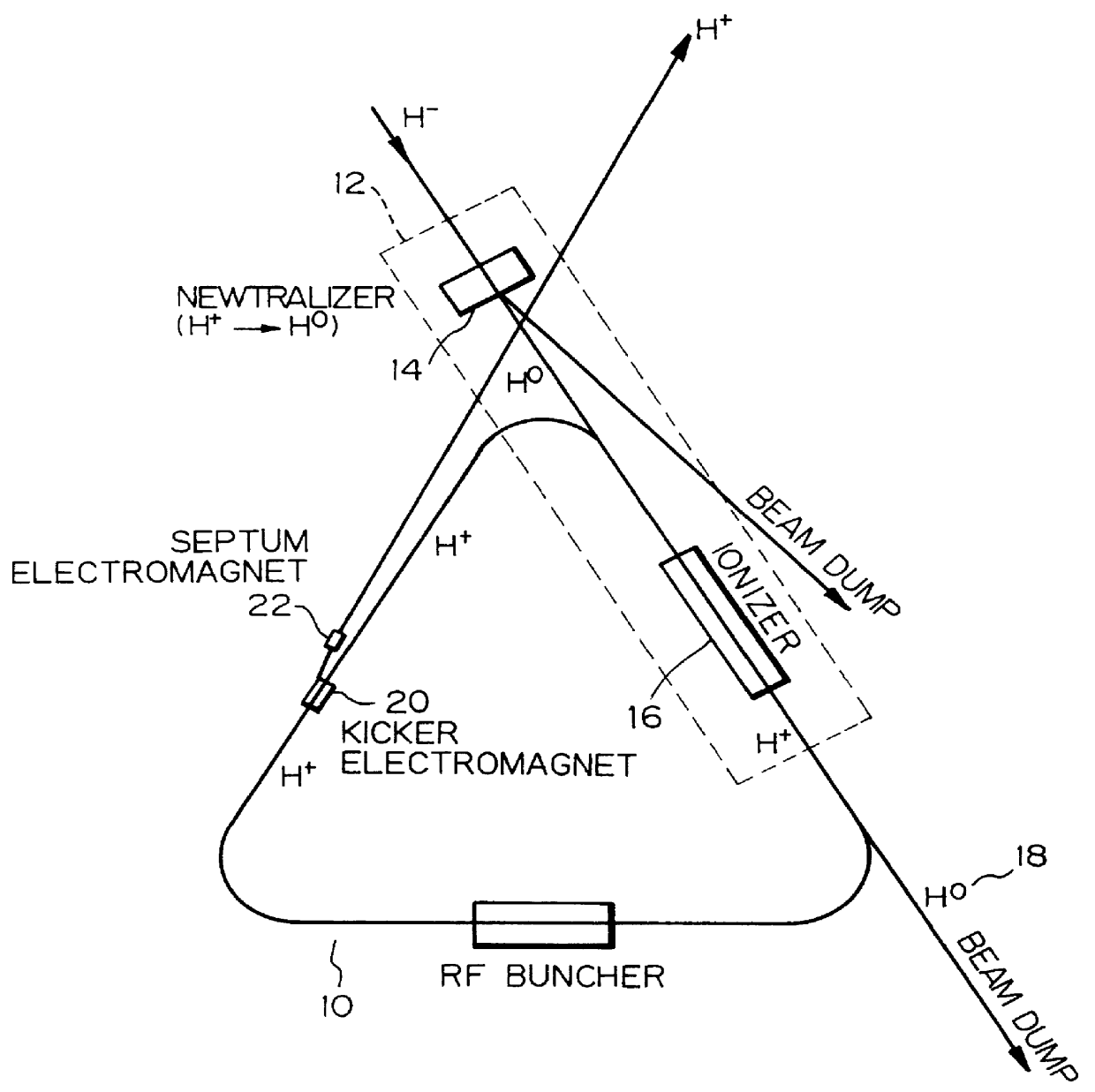
The embodiment of the present invention is the improvement of the device disclosed in JAERI-Research 97-040, 97-041 and 97-057 in that the laser output has been considerably reduced with respect of the ionizer for the injection device.

According to the embodiment of the present invention, the ionizer for the injection device consists of an undulator provided at the linear section of the ring and an optical resonator and is adapted to ionize H.sup.0. H.sup.0 beam that has been excited by the relativistic Doppler effect and the resonance absorption of the laser beam is efficiently ionized in the Lorentz electric field caused by the interaction of the relativistic velocity of the injected particles and the magnetic field. The Lorentz electric field by the undulator magnetic field is capable of remarkably increasing the efficiency of the charge-exchange of the excited hydrogen and ionizing it with the dye laser of about 485 nm, less than 1 kW. There is no scattering due to foils nor any ...


PUM


Abstract

A charge-exchange device is disclosed which is able to considerably reduce, without the use of foils, radio activation caused by a beam deflection angle and, which also implements a further efficiency and reduction of a laser output. The charge-exchange device is provided with an undulator and an optical resonator. The undulator magnetic field which has been generated by the undulator generates the Lorentz electric field by interaction with the relativistic velocity of H0 neutral beam being injected. The optical resonator amplifies the photon density of the laser beam and causes it to collide against the injected H0 neutral beam, thereby resonantly exciting the H0 beam to the principal quantum number of 4. The H0 beam which has been resonantly excited or excited by the relativistic Doppler effect in the undulator magnetic field is ionized to H+ ion by the Lorentz electric field.

Description

1) Field of the InventionThe present invention relates to a charge-exchange device.Development of powerful next-generation neutron sources is receiving general attention as a target for the development of advanced new scientific technology in the 21st century. One such project is the realization of a large-scale proton accelerator in the order of 5 MW by NSNS in U.S.A and by ESS in Europe. A proposal is also being made following the neutron study plan of the Japan Atomic Energy Research Institute to establish a multi-purpose research facility for utilizing proton beams in the order of 1.5 GeV, 8 MW with an ultra powerful super conducting linear proton accelerator as the principal facility. A storage ring for generating a very intense pulsed neutron (equivalent to 5 MW) is required for the study of neutron scattering which is one of the principal study themes. Since these accelerators and storage rings generate neutron beams having a large output which has not been experienced in the...

Claims


Application Information

Patent Timeline
Patent Type & Authority Patents(United States)
IPC IPC(8): G21K1/14G21K1/00H05H3/00H05H3/06G21G1/04H05H13/04
CPCH05H3/06G21K1/14Y02E30/10
Inventor SUZUKI, YASUO
Owner JAPAN ATOM ENERGY RES INST
Why Eureka
Try Eureka