Molecular beam epitaxy method

a beam epitaxy and beam technology, applied in the direction of crystal growth process, polycrystalline material growth, chemically reactive gas growth process, etc., can solve the problem of increasing the evaporation of deposited material from the substra

Inactive Publication Date: 2000-11-14
SHARP KK
View PDF13 Cites 25 Cited by
  • Summary
  • Abstract
  • Description
  • Claims
  • Application Information

AI Technical Summary

Benefits of technology

The present invention may thus enable positioning of the outlet of the supply conduit close as possible to the growth surface, thereby permitting the local ammonia flux to be maximized in the region of the growth surface consistent with obtaining a uniform flux over the area of the substrate, whilst avoiding keeping the outlet so close as to cause the temperature at the outlet end of the first supply conduit to reach that at which there is significant ammonia decomposition within the outlet end of the first supply conduit. Such temperature is typically about 600.degree. C. Thus, it is preferred to position the ammonia outlet and the flow of ammonia such that the temperature at the outlet does not exceed about 600.degree. C. and such that the ammonia vapour pressure at the substrate is 1 to 10.sup.-7 Pa (10.sup.-2 to 10.sup.-9 mbar), depending upon the pressure to which the vacuum pressure is evacuated. This may be facilitated by mounting the ammonia outlet so that its position relative to the substrate can be varied before or even during a particular epitaxial growth period.
The method of the present invention allows a high vacuum to be maintained within the vacuum chamber as a whole, thereby permitting high vacuum compatible equipment, e.g. effusion cells, to be used in the same vacuum chamber. In this regard, it is to be appreciated that the first supply conduit supplies ammonia which is required to be present in excess for the molecular beam epitaxial growth step, and that a conventionally positioned effusion cell may define the second supply conduit for supplying the Group III element in elemental form. This mitigates the problem of introducing impurities which can arise in cases where the Group III element is supplied to the vacuum chamber in the form of an organometallic gas which decomposes in the vacuum chamber to provide the Group III element.
In a first embodiment, the ammonia is discharged through the ammonia outlet towards the substrate in a direction which is transverse, preferably perpendicular, to that surface of the substrate on which epitaxial growth is to take place. This assists in ensuring that there is a uniform flux of the species over the area of the substrate. In this embodiment, the outlet of the first supply conduit is preferably spaced from said surface of the substrate by a distance x such that 0.1.alpha.<x<0.7.alpha., where .alpha. is the distance between the surface of the substrate and the outlet of the second supply conduit. More preferably, 0.2.alpha.<x<0.5.alpha., and most preferably x is about 0.4.alpha..

Problems solved by technology

However, even such a modified CVD technique requires high growth temperatures to promote a high quality epitaxial deposit with all the attendant disadvantages of high growth temperatures, such as liberation of unwanted contaminants and increased evaporation of deposited material from the substrate.

Method used


Image

  • Molecular beam epitaxy method
  • Molecular beam epitaxy method

Examples


Embodiment Construction

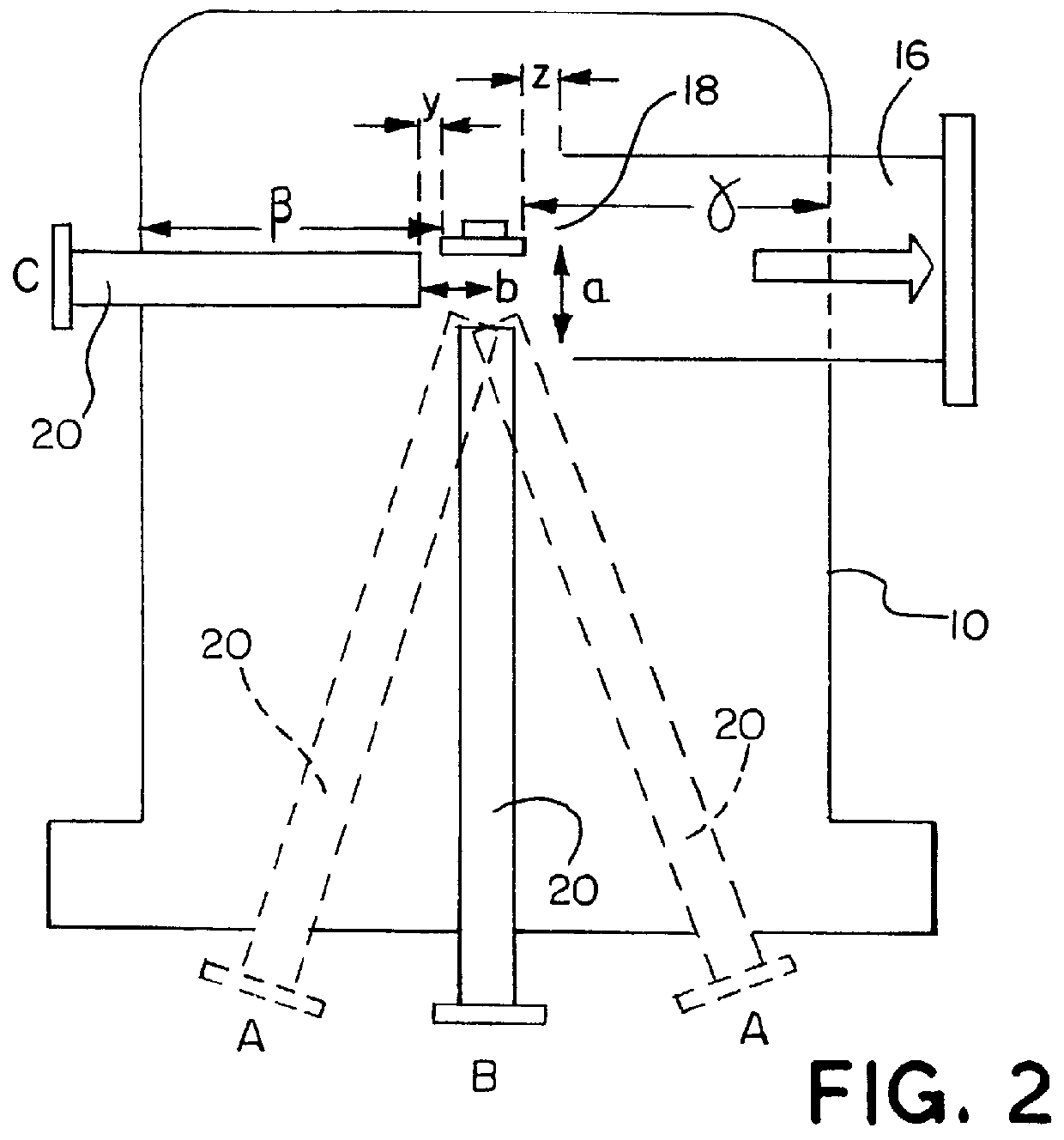
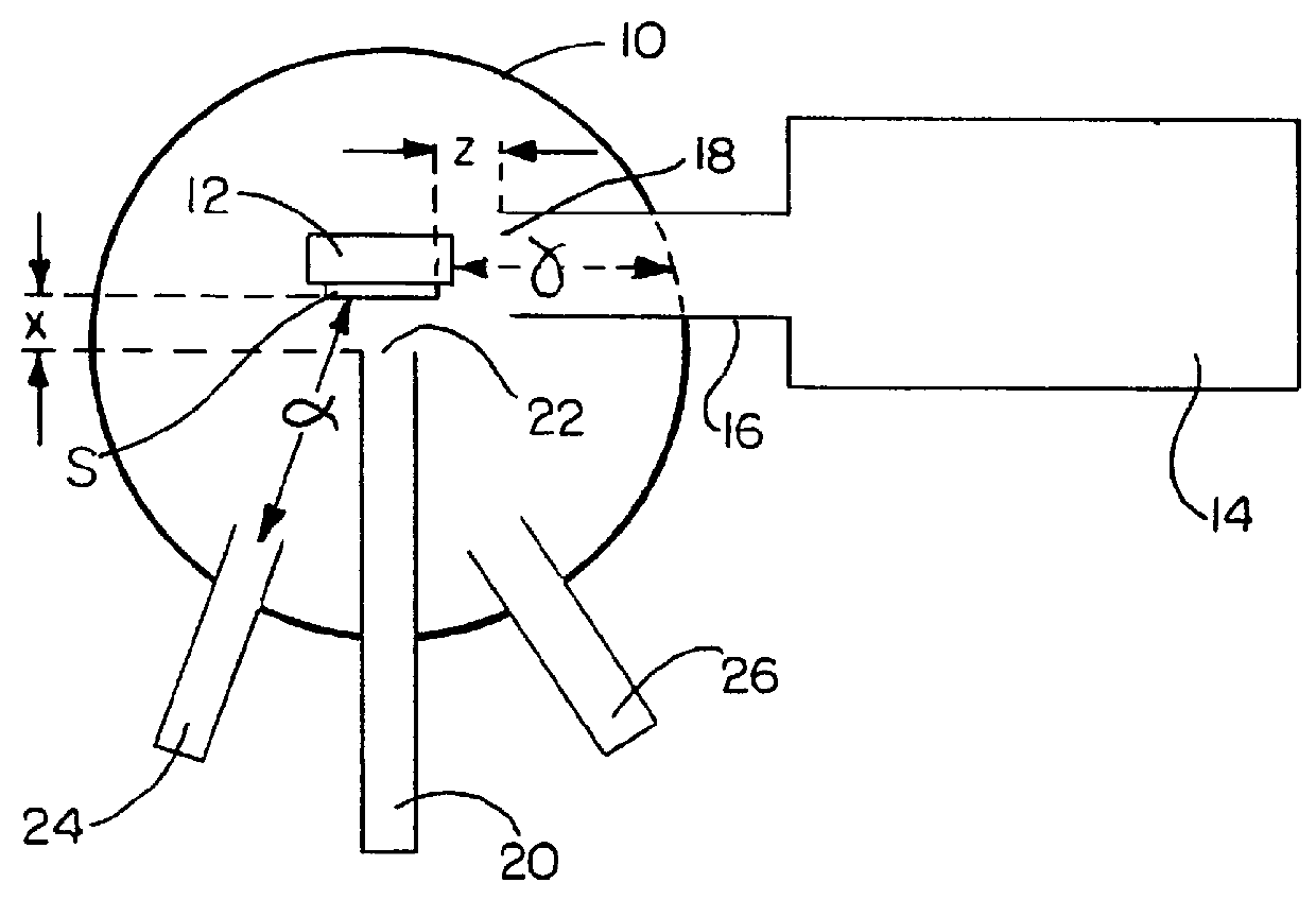
Referring now to FIG. 1, the apparatus is for the epitaxial deposition of GaN-type semiconductor material by molecular beam epitaxy in a research system and comprises a vacuum chamber 10 in which is disposed a heated support 12 arranged to support and heat a substrate S. The vacuum chamber 10 is connected with an ultra-high vacuum pump 14 via an exhaust conduit 16 which extends into the vacuum chamber 10. The inner end of the exhaust conduit 16 defines a vacuum outlet 18 of the vacuum chamber 10. Such vacuum outlet 18 is disposed adjacent to the substrate support 12. In this particular embodiment, the vacuum outlet 18 is spaced a distance z of about 30 mm from the adjacent side edge of the substrate S on the support 12 so that the exhaust conduit 16 extends in a directin substantially parallel to the plane of the surface of the substrate S upon which epitaxial growth is to take place. This distance z represents about 0.1.gamma., where .gamma. is the distance between said adjacent si...


PUM

PropertyMeasurementUnit
temperatureaaaaaaaaaa
pressureaaaaaaaaaa

Abstract

A method of growing a layer of Group III nitride material on a substrate by molecular beam epitaxy includes the steps of (i) disposing a substrate in a vacuum chamber, (ii) reducing the pressure in the vacuum chamber to a pressure suitable for epitaxial growth by molecular beam epitaxy, (iii) supplying ammonia through an outlet of a first supply conduit into the vacuum chamber so that the ammonia flows towards the substrate; and (iv) supplying a Group III element in elemental form through an outlet of a second supply conduit into the vacuum chamber so that said Group III element flows towards the substrate. The method causes a layer containing Group III nitride to be grown on the substrate by molecular beam epitaxy. In the method, the outlet of the first supply conduit is disposed nearer to the substrate than the outlet of the second supply conduit.

Description

This invention relates to a molecular beam epitaxy (MBE) method for the epitaxial growth of Group III nitride semiconductor materials, such as GaN.The epitaxial growth of Group III nitride semiconductor materials on a substrate can be effected by molecular beam epitaxy (MBE) or by chemical vapour deposition (CVD) which is sometimes known as Vapour Phase Epitaxy (VPE).BACKGROUND OF INVENTIONCVD (or VPE) takes place in an apparatus which is commonly at atmospheric pressure but sometimes at a slightly reduced pressure of typically about 10 KPa. Ammonia and the species providing one or more Group III elements to be used in epitaxial growth are supplied substantially parallel to the surface of a substrate upon which epitaxial growth is to take place, thus forming a boundary layer adjacent to and flowing across the substrate surface. It is in this gaseous boundary layer that decomposition to form nitrogen and the other elements to be epitaxially deposited takes place so that the epitaxial...

Claims


Application Information

Patent Timeline
Patent Type & Authority Patents(United States)
IPC IPC(8): C30B23/02C30B23/08C30B29/38H01L21/203
CPCC30B23/02C30B29/406C30B29/403Y10T117/10
Inventor HOOPER, STEWART EDWARDKEAN, ALISTAIR HENDERSONDUGGAN, GEOFFREY
Owner SHARP KK
Why Eureka
Try Eureka