Contour-following apparatus for cleaning surfaces

a technology of cleaning apparatus and surface, which is applied in the field of working apparatus, can solve the problems of affecting the performance of the ship, requiring replacement, and deteriorating of the most durable coating, and achieving the effects of improving the service life of the ship, corrosion and metal fatigue, and improving the service li

Inactive Publication Date: 2001-02-20
REMOTE TOOLS
View PDF12 Cites 38 Cited by
  • Summary
  • Abstract
  • Description
  • Claims
  • Application Information

AI Technical Summary

Benefits of technology

The gimbals assembly with the instrument carriage is an important feature of the present invention. The gimbals assembly has two pivots located on the perimeter of the instrument carriage. For optimum cleaning efficiency, the instrument carriage is preferably maintained approximately parallel to, and in contact with, the work surface. The locations of the pivots ensure that the instrument carriage always remains normally in contact with the work surface, whether that surface is planar or curved. In addition, the pivots allow the instrument carriage to pivot independently about two orthogonal axes, thereby furthering alignment with the work surface. Since the instrument carriage is freely pivotable, neither operator interaction nor computer control is needed to keep it properly aligned with the work surface.
Still another feature of the present assembly is the swivel base of the positioning assembly. The positioning assembly is pivotable about a vertical axis to allow movement to different sides of the delivery vehicle. This features allows placement of the instrument carriage up against the ship's support blocks without interference from the delivery vehicle.
Yet another feature of the present invention is its modular construction and its ease of disassembly / reassembly. The major components of the apparatus, including the contour following assembly, are attached to each other with clevis pins and retainer pins which can readily be removed without the use of special tools. The contour following assembly can thereby be readily dismantled into individual weldments, carried to another location, and as readily reassembled for use. This feature also reduces down-time of the apparatus, since individual components that are removed for repairs or servicing can be easily replaced.

Problems solved by technology

However, even the most durable coatings eventually deteriorate and must be replaced to prevent corrosion of the hull.
Roughness caused by barnacles and other marine growth, degradation of hull coatings, and deterioration of propeller surfaces can adversely affect the performance of the ship.
Fouling also affects the hull coating material, eventually leading to corrosion and metal fatigue.
Corrosion damage can result in expensive repairs, downtime, and, in severe cases, to premature scrapping of the ship.
Although sand blasting is widely used, it has several disadvantages including abrasion to the skin of the personnel performing the blasting, an increase in the amount of materials which must be recovered and disposed of, and undesired metallurgical changes to the steel surface being impacted by the silica particles.
Manual cleaning is both dangerous and time consuming: the operators must work by hand with ultra-high pressure water jet wands that can produce thrusts as high as 50 pounds.
The kinetic energy of the ultra-high pressure water can easily cut and lacerate human flesh, making the hand-held wands very dangerous to use.
However, these types of apparatus are less useful for cleaning curved areas such as the bow, stern, and bottom of a ship, the bottom of an aircraft fuselage, or the walls of a storage tank, where effective cleaning depends on the ability to follow the surface contour.
Therefore, many dry docks and aircraft maintenance facilities still resort to costly, potentially-dangerous manual cleaning techniques for at least part of the surface maintenance process.

Method used


Image

  • Contour-following apparatus for cleaning surfaces
  • Contour-following apparatus for cleaning surfaces
  • Contour-following apparatus for cleaning surfaces

Examples


Embodiment Construction

In the following detailed description, reference numerals are used to identify structural elements, portions of elements, surfaces and areas in the drawings. It should be understood that like reference numerals are intended to identify the same structural elements, portions or surfaces consistently throughout the several drawing figures, as such elements, portions or surfaces may be further described or explained by the entire written specification. As used in the following description, the terms "horizontal," "vertical," "left," right," "up," "down," as well as adjectival and adverbial derivatives thereof (e.g., "horizontally," "rightwardly," "upwardly," etc.) refer to the relative orientation of the illustrated structure as the particular drawing figure faces the reader. Similarly, the terms "inwardly" and "outwardly" refer to the orientation of a surface of revolution relative to its axis.

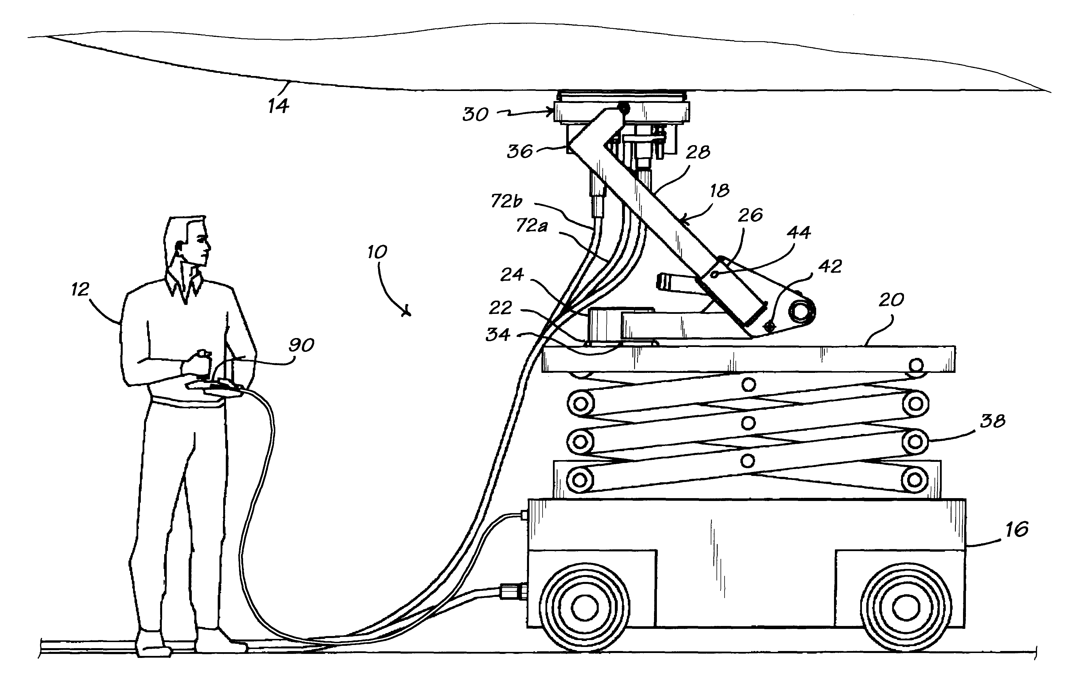
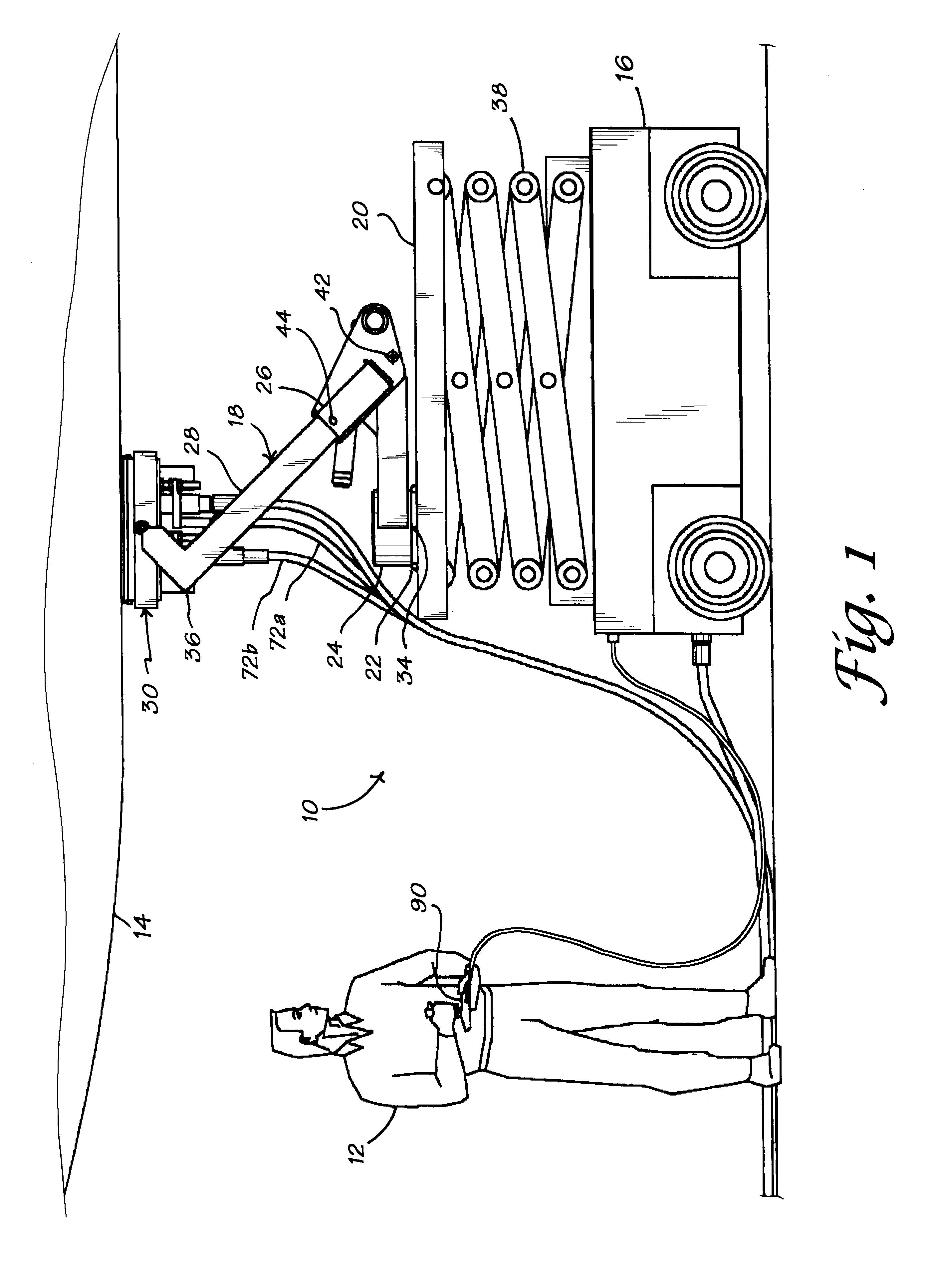
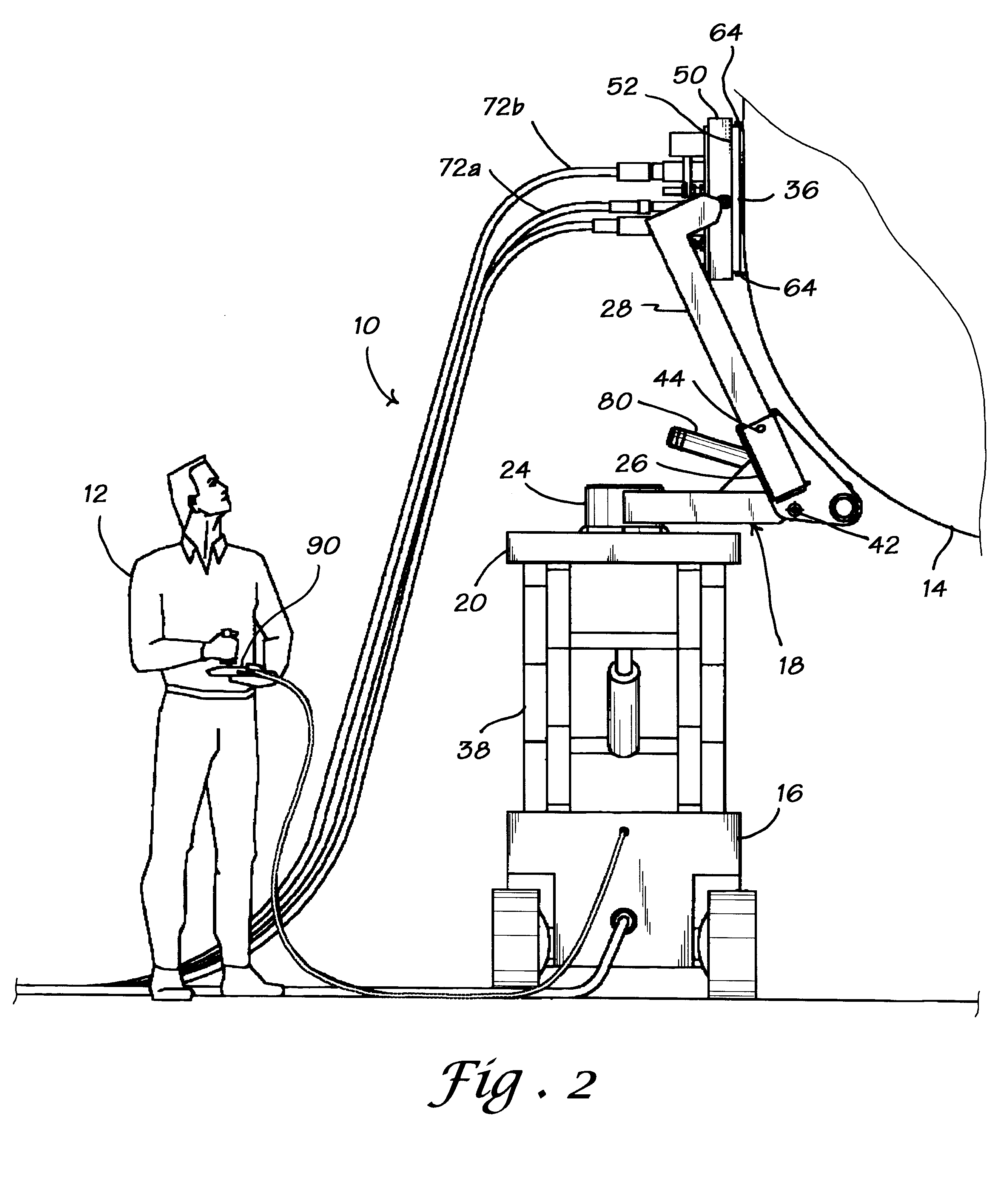
Referring now to FIGS. 1 and 2, there is shown a modular, contour-following apparatus 10 acc...


PUM


Abstract

A modular apparatus for supporting and guiding a tool such as an ultra-high pressure water jet along a work surface, including a contour following assembly attached to a motorized lift vehicle. The contour following assembly includes a gimbals assembly with an instrument or tool carriage assembly, a positioning assembly that urges the gimbals assembly and the instrument carriage against the surface, and, optionally, a hydraulic, mechanical, or pneumatic pressure system that applies pressure to the positioning assembly. A scissors lift, hydraulic lift, telescoping arm, or other suitable device raises and lowers the apparatus. In operation, the gimbals assembly and the positioning assembly cooperate to maintain the instrument carriage in a user-selected position with respect to a work surface such as a ship hull, aircraft fuselage, storage tank, or the like. Depending on the type of tool selected, the apparatus may be used for cleaning or stripping surface coatings, buffing, painting, washing, and so forth. The apparatus is mobile, compact, cost-effective, and can be operated by a single operator.

Description

1. Field of the InventionThe present invention relates to an apparatus for working on the surfaces of ship hulls, aircraft fuselages, barges, storage tanks, and the like. In particular, the present invention relates to a contour-following apparatus for supporting and guiding tools such as ultra-high pressure water sprayers, sand and grit blasters, paint sprayers, and lasers.2. Discussion of BackgroundThe shipping industry is a vital and growing part of the global economy. At least 25,000 oceangoing vessels of weight 1,000 gross tons or more are presently in operation (this estimate does not include vessels that operate exclusively on inland waterways, military vessels, and special-purpose vessels such as icebreakers and cable ships. (The terms "ship" and "vessel" are used herein to refer to all watercraft, including boats, barges, tankers, cargo ships, freighters, cruisers, container ships, submarines, tankers, supertankers, aircraft carriers, and so forth.)The external surfaces of ...

Claims


Application Information

Patent Timeline
Patent Type & Authority Patents(United States)
IPC IPC(8): B05B13/00B64F5/00B63B59/00B63B59/06B24C3/06
CPCB05B13/005B24C3/06B63B59/06B64F5/0018B63B2059/065B64F5/30
Inventor APPEL, D. KEITHECKSTEIN, STEVEN L.
Owner REMOTE TOOLS
Why Eureka
Try Eureka