Thermal printing head, process for producing thermal printing head, recorder, sinter and target

a printing head and thermal printing technology, applied in the field can solve the problems of impairing the properties of thermal printing heads, corroding electrodes or heat-generating resistors, and hardly removing the heat-generating resistor layer, so as to reduce the dispersion of foreign matter, enhance density, and reduce the effect of pores

Inactive Publication Date: 2001-03-13
KK TOSHIBA
View PDF14 Cites 24 Cited by
  • Summary
  • Abstract
  • Description
  • Claims
  • Application Information

AI Technical Summary

Benefits of technology

According to the thermal printing head of the first aspect of the invention, the protective layer for covering the heat-generating resistor and the electrode is formed by using sputtering with the sinter of powder comprising silicon nitride, silicon dioxide and magnesium oxide having an average particle diameter of 1.0 .mu.m or below used as a target, so that a foreign matter (splash) due to the target can be prevented from being produced, and the protective layer can be produced with the foreign matter prevented from being captured.
With the sinter according to the eighth aspect of the invention and the target according to the tenth aspect of the invention, by adding the magnesium oxide having an average particle diameter of 1.0 .mu.m or below, preferably an average particle diameter of 0.1 to 0.5 .mu.m, pores formed on the sinter and the target can be decreased, and a density can be increased to the neighborhood of the theoretical density. The magnesium oxide is added to be 0.01 to 5.0% by weight, more preferably 0.1 to 0.5% by weight of the powder to be the material for the sinter and the target. When the added amount of the magnesium oxide to the powder to be the material for the sinter and the target is 0.01% by weight or below, it is hard to conspicuously improve the densities of the sinter and the target. And, when the added amount of the magnesium oxide to the powder is 5.0% by weight or more, the densities of the sinter and the target are lowered with the addition of the magnesium oxide, and the hardness of the film formed from the target is lowered. And, as to a ratio of silicon nitride and silicon dioxide in the powder, silicon nitride is 65 to 80% by weight in the powder, and silicon dioxide is 35 to 20% by weight in the powder. In sintering the powder, the powder is preferably adjusted to have an average particle diameter of 10 .mu.m or below, and more desirably about 1 .mu.m or below. Thus, by adjusting the particle diameter of the powder, the densities of the sinter and the target can be further made closer to the neighborhood of the theoretical density.

Problems solved by technology

Especially, the sinter, which is used as the target, is a problem as the cause to produce the foreign matter.
However, when the protective layer and the primary layer for the heat-generating resistor are formed by the sputtering process or the like, the foreign matter which is dispersed from the sinter used as the target to adhere to the protective layer and the primary layer for the heat-generating resistor is hardly removed.
Moisture, a corrosive substance or the like is easy to enter into the pinhole and the broken part of the protective layer formed as described above to cause a problem that the electrode or the heat-generating resistor is corroded or deteriorated, resulting in impairing the properties of the thermal printing head.
And, if the foreign matter were captured into the primary layer for the heat-generating resistor, the heat-generating resistor layer and the like formed on the primary layer for the heat-generating resistor particularly suffers from a defect and has drawbacks that the heat-generating resistor has a defect in its property such as a resistance value and its quality such as service life.
In addition, there was a problem that quality of an image printed on a printing medium by a recorder was degraded because quality such as the feature or service life of the thermal printing head mounted on the recorder was affected.

Method used


Image

  • Thermal printing head, process for producing thermal printing head, recorder, sinter and target
  • Thermal printing head, process for producing thermal printing head, recorder, sinter and target
  • Thermal printing head, process for producing thermal printing head, recorder, sinter and target

Examples


example 3

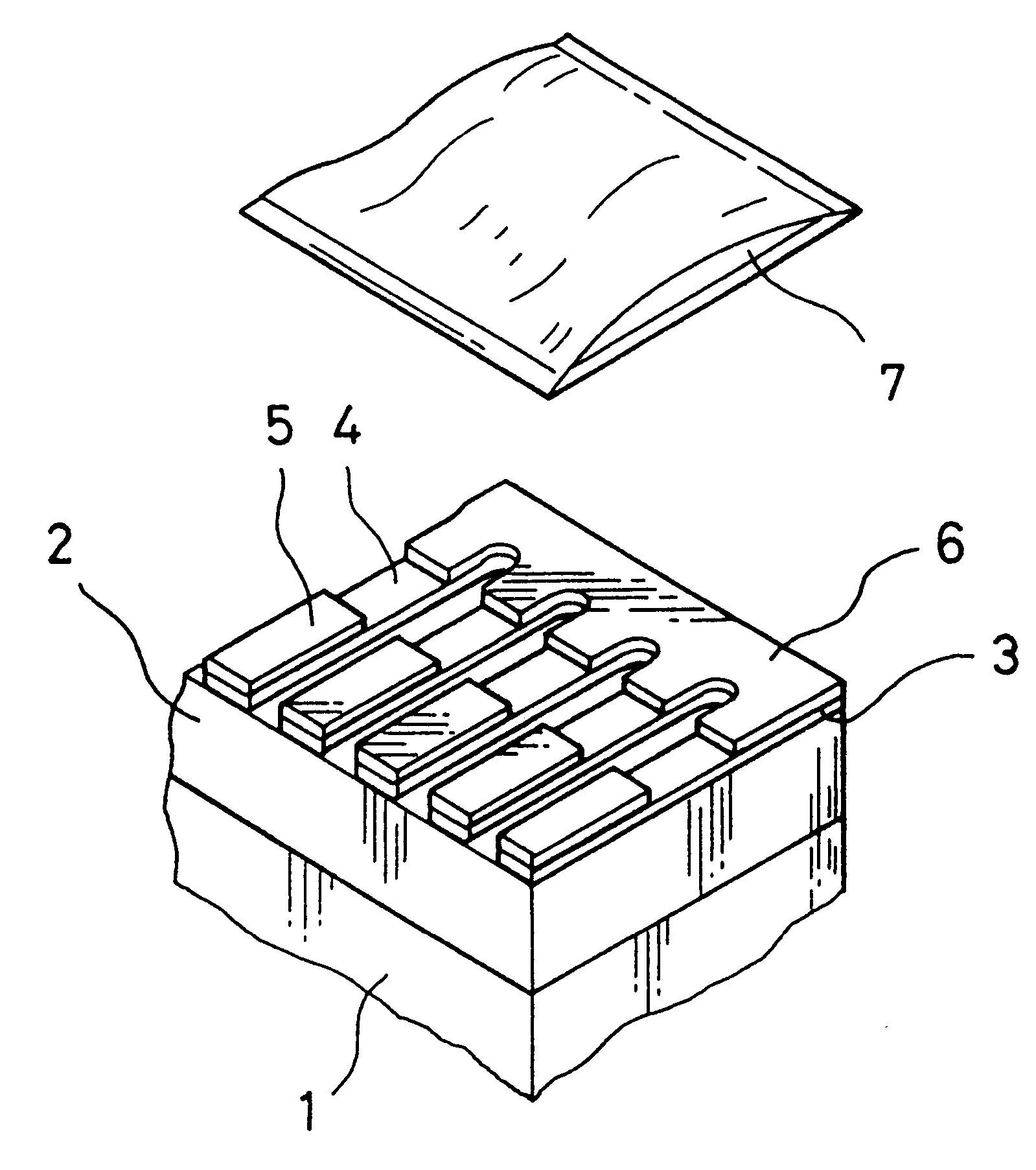
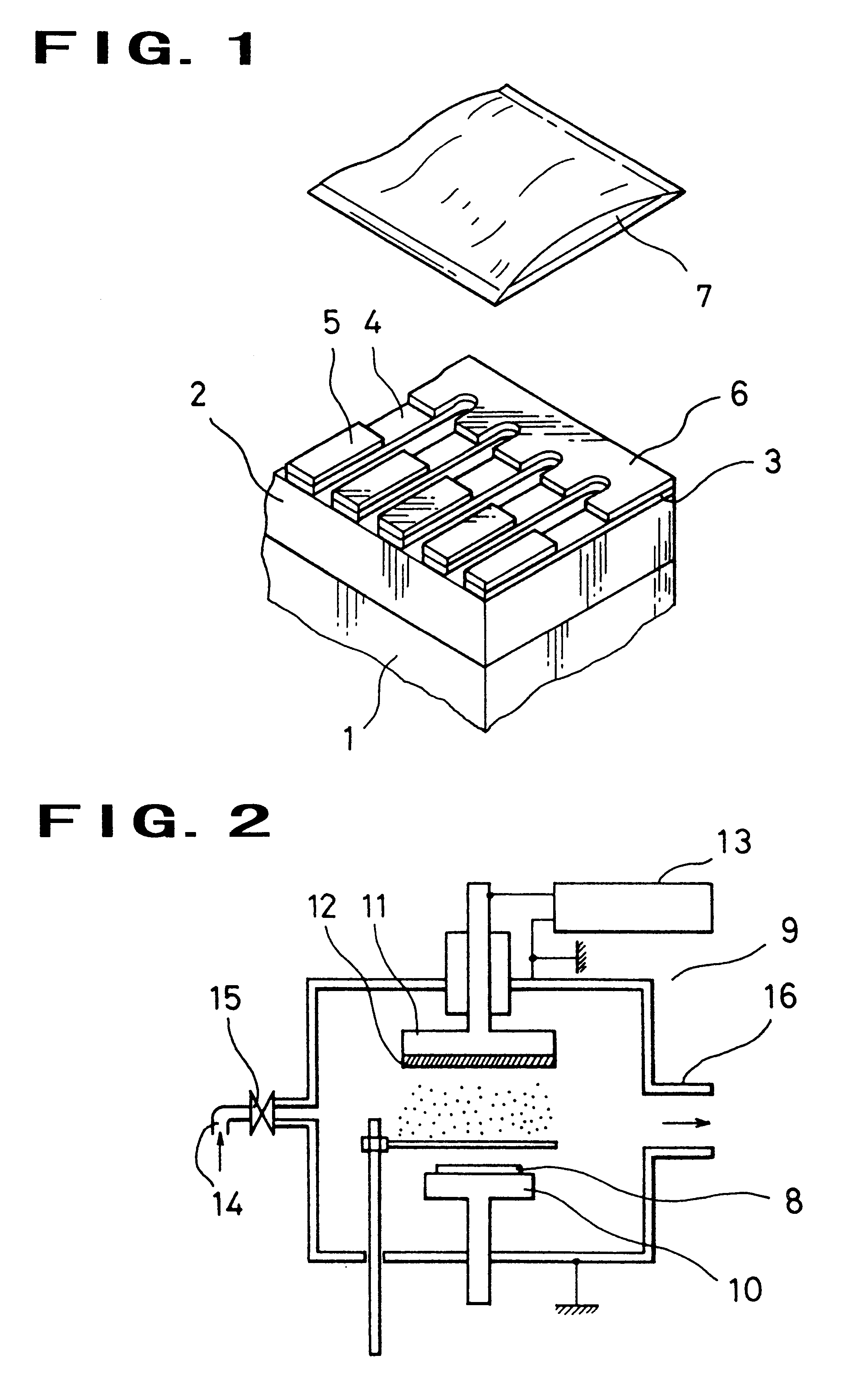
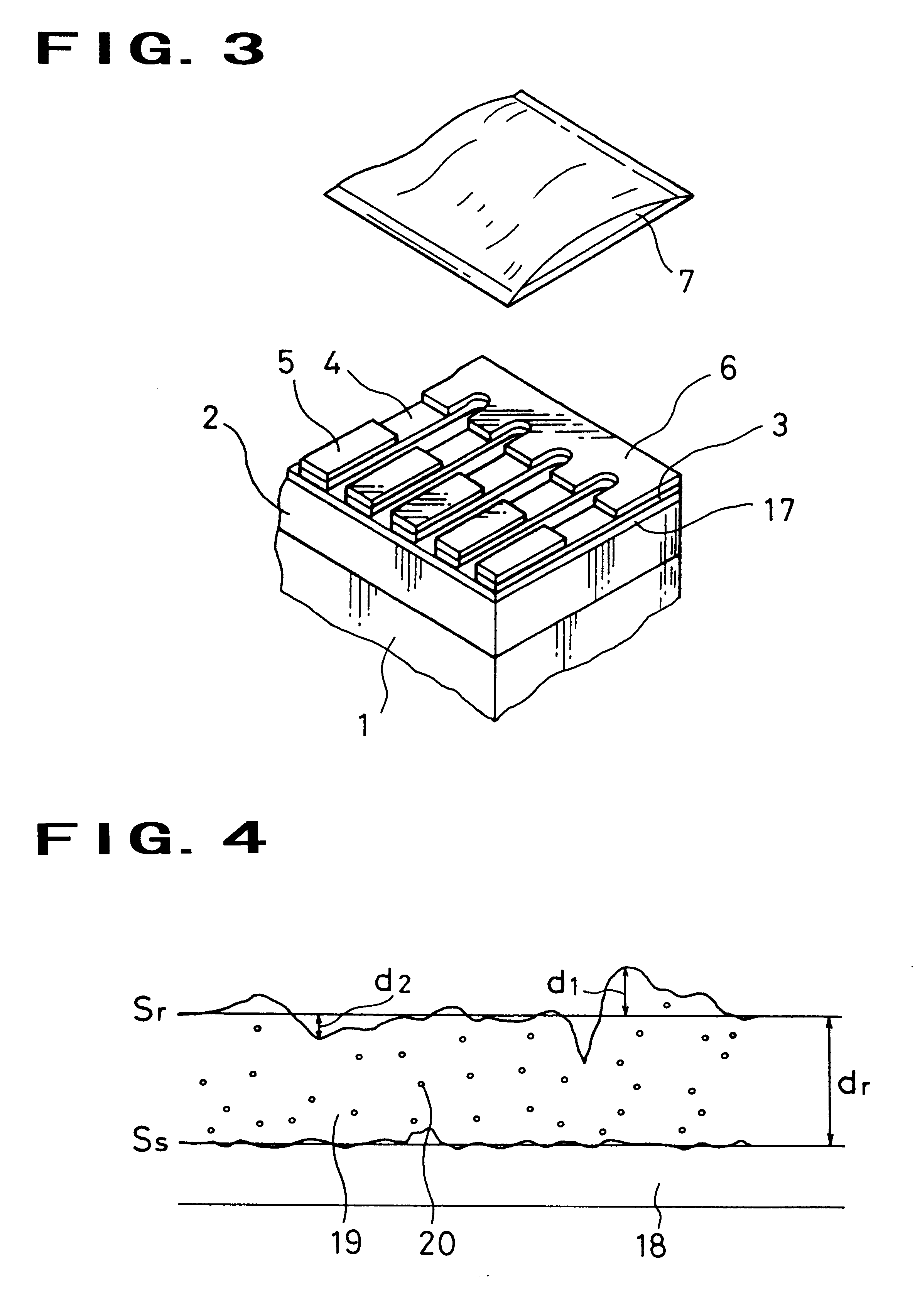
The thermal printing head shown in FIG. 1 was produced. Specifically, a glaze glass layer 2 comprising silicon dioxide was disposed on an alumina-ceramics supporting substrate 1. Then, a heat-generating resistor layer 3 comprising Ta--SiO.sub.2 was formed on the glaze glass layer 2. Separate electrodes 5 and a common electrode 6 formed of Al--Si were formed by a photoengraving process so that a heat-generating part 4 was formed on the heat-generating resistor layer 3. And, a protective layer 7 for covering the heat-generating part 4, the separate electrodes 5 and the common electrode 6 was formed as follows.

First, powder comprising 74.6% by weight of silicon nitride having an average particle diameter of 1 .mu.m, 24.9% by weight of silicon dioxide having an average particle diameter of 1 .mu.m and 0.5% by weight of magnesium oxide having an average particle diameter of 0.05 .mu.m was mixed in respective ball mills to prepare sintering materials. The silicon nitride and the magnesium...


PUM

PropertyMeasurementUnit
particle diameteraaaaaaaaaa
average particle diameteraaaaaaaaaa

Abstract

A process for producing a protective layer or a primer layer for a heat-generating resistor for a thermal head by sputtering using a target comprising a sinter of a silicon nitride / silicon dioxide / magnesium oxide powder. By regulating the particle diameter of the powder, the target is prevented from suffering partial peeling during the sputtering.

Description

The invention relates to a thermal printing head to be used for various types of office automation equipment represented by a facsimile or stencil printing, a process for producing the thermal printing head, a recorder using the thermal printing head, a sinter suitably used to form a protective layer and a primer layer for a heat-generating resistor configuring the thermal printing head, and a target.Recently, the thermal printing head, which has advantages such as a low noise, a low maintenance cost and a low running cost, is extensively used for thermal recorders of various types of OA equipment such as a facsimile or stencil printing.Generally, the thermal printing head has the following structure. Specifically, a glaze glass layer is formed on an alumina substrate, a heat-generating resistor layer and a conductive layer such as aluminum are formed on the glaze glass layer, and a heat-generating resistor and an electrode are formed by a photoengraving process. Besides, it has a s...

Claims


Application Information

Patent Timeline
Patent Type & Authority Patents(United States)
IPC IPC(8): B41J2/335B41J2/16C04B35/622C23C14/34
CPCB41J2/1601B41J2/1646B41J2/3353B41J2/3355B41J2/3357B41J2/3359C04B35/62222C23C14/3414
Inventor KITAZAWA, YUSUKETAKAMURA, YASUHISA
Owner KK TOSHIBA
Why Eureka
Try Eureka