Air actinism chamber apparatus and method

a technology of air actinism and chamber, which is applied in the field of ultraviolet ray actinism chamber, can solve the problems of reducing the output and service life of conventional uvc products, destroying viable organisms, and reducing the effectiveness of uvc and hvac systems, so as to enhance the bulb life of a uv bulb, and shorten the lamp length

Inactive Publication Date: 2001-04-24
PHASYC
View PDF40 Cites 94 Cited by
  • Summary
  • Abstract
  • Description
  • Claims
  • Application Information

AI Technical Summary

Benefits of technology

Accordingly, it is a primary object of the present invention to provide an ultraviolet ray actinism chamber for destroying contaminants thereby.
Another object of the present invention is to provide increased UV bandwidth to so increase the "killing" power of the UV system.
Another object of the present invention is to increase UV reflectivity in and around the UV bulbs to enhance the UV irradiation.
Another object of the present invention is to provide better, yet shorter lamp lengths to fit in conventional HVAC systems.
Yet another object of the present invention is to enhance the bulb life of a UV bulb for such a system.
Viewed from a second vantage point, it is an object of the present invention to provide a method for sterilizing air, the steps including, passing the air adjacent a source of ultraviolet light, and resisting temperature drop of the ultraviolet light caused by the passage of the air.

Problems solved by technology

However, certain conditions found within the air handling systems drastically reduced UVC performance.
Moving air, especially below 77.degree. F., over the tubes decreased the output and service life of conventional UVC products and thus their ability to destroy viable organisms.
The use of UVC and HVAC systems virtually disappeared over the next decade due to the introduction of new drugs, sterilizing cleaners and control procedures combined with the performance problems of UVC lamps and air handling systems (reduced output, short tube life, and high maintenance).
However, from testing it can be seen that the destructive potential of a combination of UVC and ozone for system components is detrimental.
In 1974, research concluded that during such cleaning, the partial pressure of O.sub.2 decreased and that of CO.sub.2 and H.sub.2 O increased, suggesting breakdown.
Therefore, radiation emission below 200 nm was found undesirable.
Thus, when both wave lengths are present, ozone is continually being formed and destroyed.
Unfortunately, previously existing lamps operated between 250 nm and 258 nm, peaking at 254 nm, missing out on the optimal 265 nm goal.
With regard to HVAC systems, biological contaminants are difficult to control because they grow in our moist, indoor environment.
While this is an important element of cleaning air, this has its problems.
Most filters are inadequate because of the many organisms that pass right on through the filter.
Also, any organisms that collect on the filter can form germ colonies that may soon contaminate passing air.
Further, if the filter should be too efficient, it blocks the passage of air and creates back pressure, causing the blower to struggle to move air through the system.
Furthermore, when the system is turned off, natural temperature differences between the system and indoor air spaces cause convection or back draft flow into the supply ducts (bypassing the filter).
This causes contaminants to be pulled back into the duct work, implanting microbes in the air flow duct cavity.
These new cultures become added sources of contaminant.
But this has its draw backs also.
Further, if the system is being treated for severe contamination such as legionela, an acid wash of the coil is common.
This is not only expensive, but can shorten the life of the equipment.
Furthermore, all biocide used in the ducts are chemical based, leaving potential toxic vapors and chemical pollutants circulating in the system as well.

Method used


Image

  • Air actinism chamber apparatus and method
  • Air actinism chamber apparatus and method
  • Air actinism chamber apparatus and method

Examples


Embodiment Construction

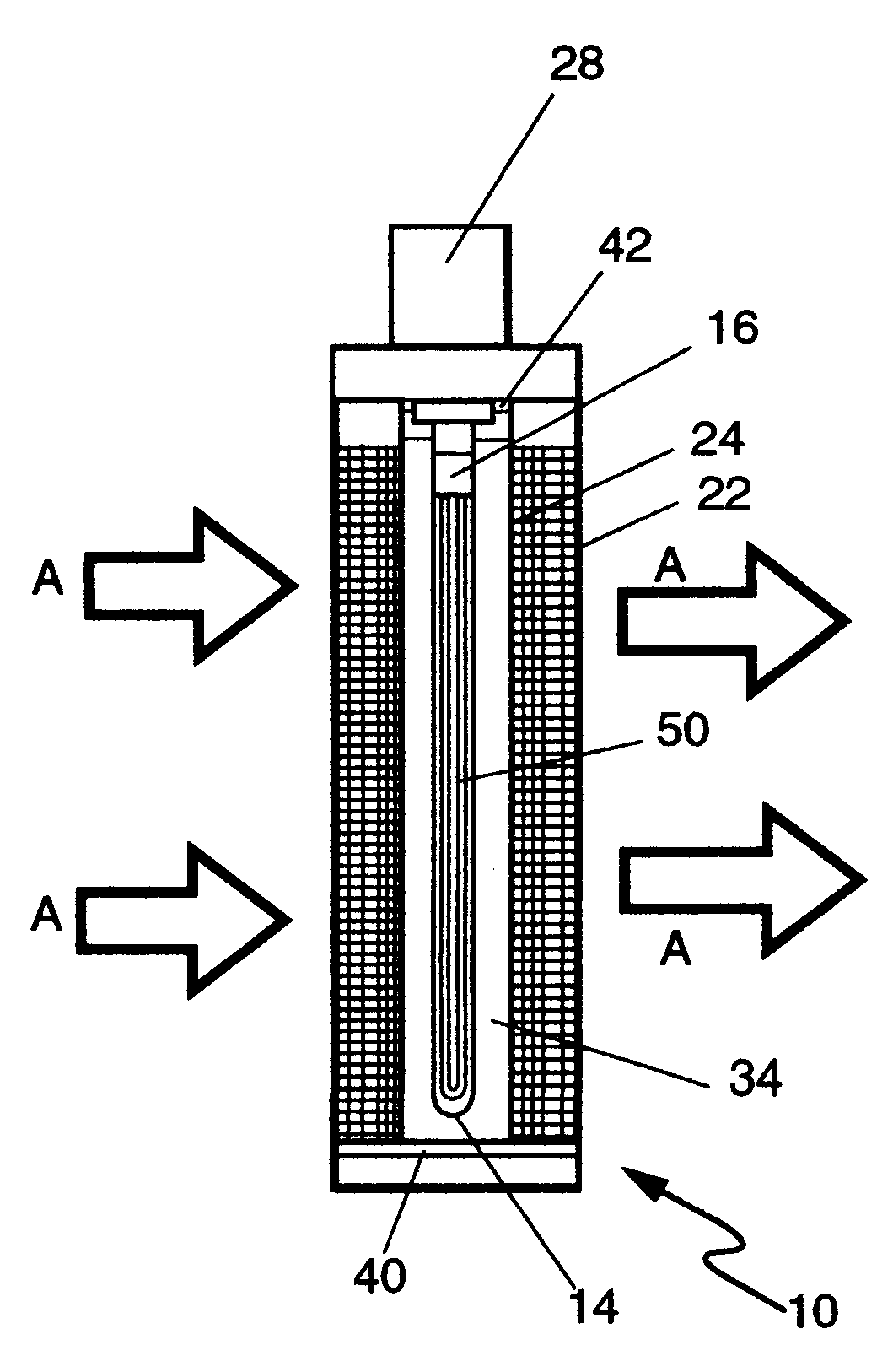
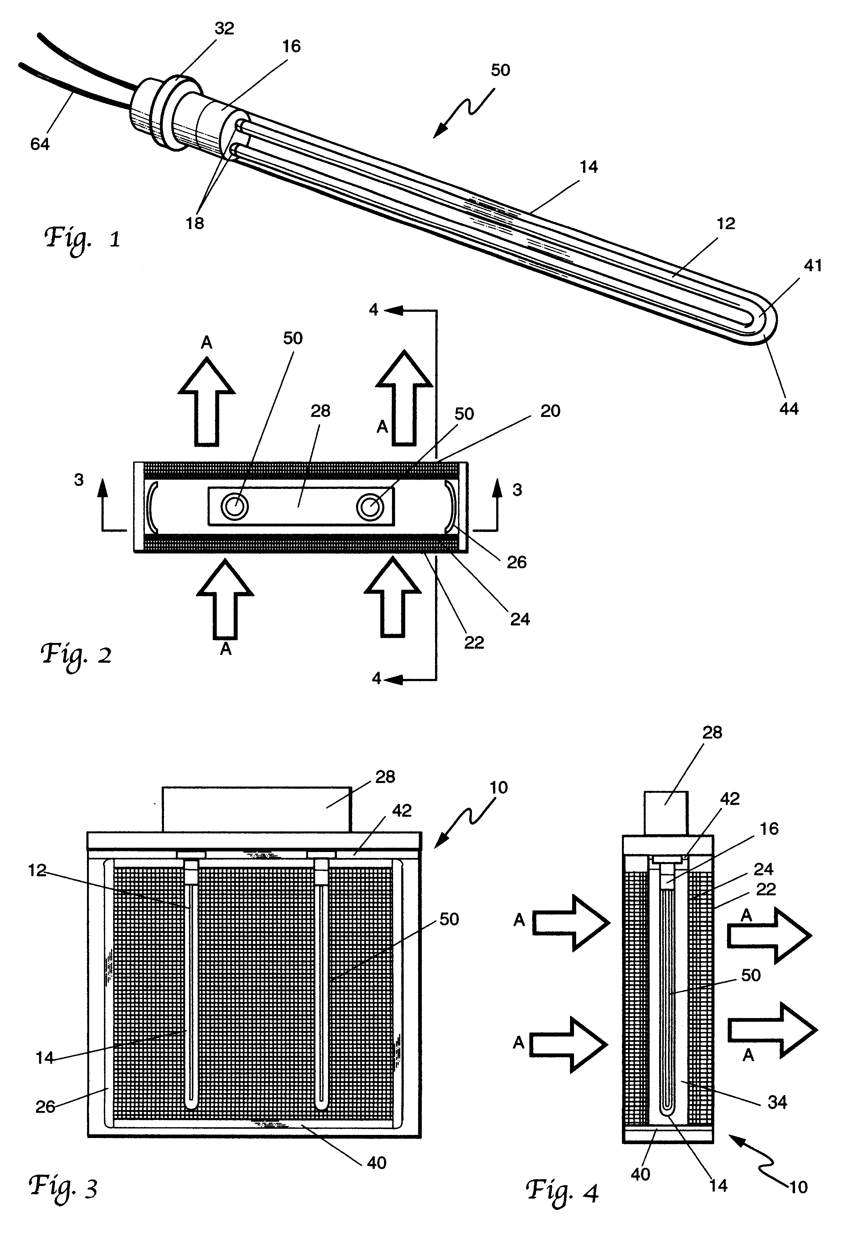
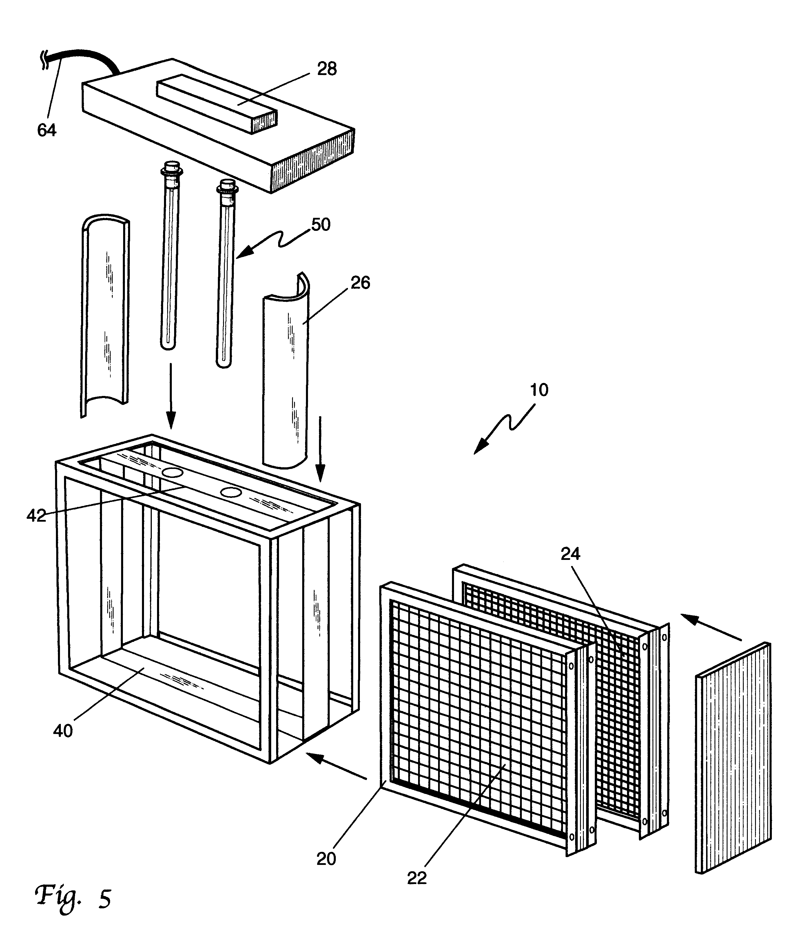
Considering the drawings, wherein like reference numerals denote like parts throughout the various drawing figures, reference numeral 10 is directed to the air actinism chamber according to the present invention.

The invention consists of three main components: UV lamp 50, photon chamber 34 and filters 20. Each component will be described more particularly below.

As seen in FIGS. 1 and 8, UV lamp 50 consists of a U-shaped UV quartz, ruby, or sapphire crystal 12 (with quartz being preferred), a quartz sheath 14, lamp coupling overlay 16, lamp base 32, U-shaped bulb gases 41, and lamp gas 44. U-shaped bulb 12 is preferably a quartz glass tube up to fifty inches long that is bent at the center to form a U-shaped bulb filled with one or more of the following: mercury, argon, iron, gallium, xenon or krypton. Aluminum metal or ceramic material is machined for the base 32 of the lamp for holding both the lamp tube 12 and electrode igniters 18. That, preferably aluminum coupling 16 allows for...


PUM

PropertyMeasurementUnit
temperatureaaaaaaaaaa
operating temperatureaaaaaaaaaa
wavelengthaaaaaaaaaa

Abstract

An apparatus and method for ultraviolet irradiation of air for the purpose of removing contaminants from that air is disclosed. A U-shaped ultraviolet bulb enshrouded within a quartz tube provides enhanced contaminant destruction characteristics. By combining a plurality of those bulbs in a chamber that is of polished aluminum, and further combining aluminum filters therewith, added irradiation enhancement is achieved.

Description

This invention relates generally to air cleansing devices. More particularly, this invention relates to ultraviolet irradiation and filtration devices.Ultraviolet (UV) light in the form of germicidal lamps has been used since the early 1900's to kill the same types of microorganisms that typically cause the same types of problems today. Since then, UV radiation in the short wave or C band range (UVC) has been used in a wide range of germicidal applications to destroy bacteria, mold, yeast and viruses. After World War II, the use of UVC rapidly increased. UVC is generally understood to exist in the 180 nm to 280 nm wave length area. Typical examples included hospitals, beverage production, meat storage and processing plants, bakeries, breweries, pharmaceutical production and animal laboratories; virtually anywhere microbial contamination was of concern. Early UVC strategies primarily consisted of an upper air approach. This method directed a beam across the ceiling of a room.During t...

Claims


Application Information

Patent Timeline
Patent Type & Authority Patents(United States)
IPC IPC(8): A61L9/18A61L9/20A62B29/00
CPCA61L9/20A62B29/00
Inventor BIGELOW, WIL
Owner PHASYC
Why Eureka
Try Eureka