
Emitter material for cathode ray tube having at least one alkaline earth metal carbonate dispersed or concentrated in a mixed crystal or solid solution

a technology of alkaline earth metal carbonate and emitter material, which is applied in the manufacture of discharge tube main electrodes, electric discharge tubes/lamps, electrode systems, etc., can solve the problems of inability to maintain sufficient lifetime and inability to employ conventional emitter materials, and achieves a larger screen size, higher brightness, and the effect of improving the quality of the material

Inactive Publication Date: 2001-04-24
PANASONIC CORP
View PDF22 Cites 8 Cited by
  • Summary
  • Abstract
  • Description
  • Claims
  • Application Information

AI Technical Summary

Benefits of technology

The object of the present invention is to provide an emitter material for a CRT aiming at a larger screen size, higher brightness, and higher resolution.
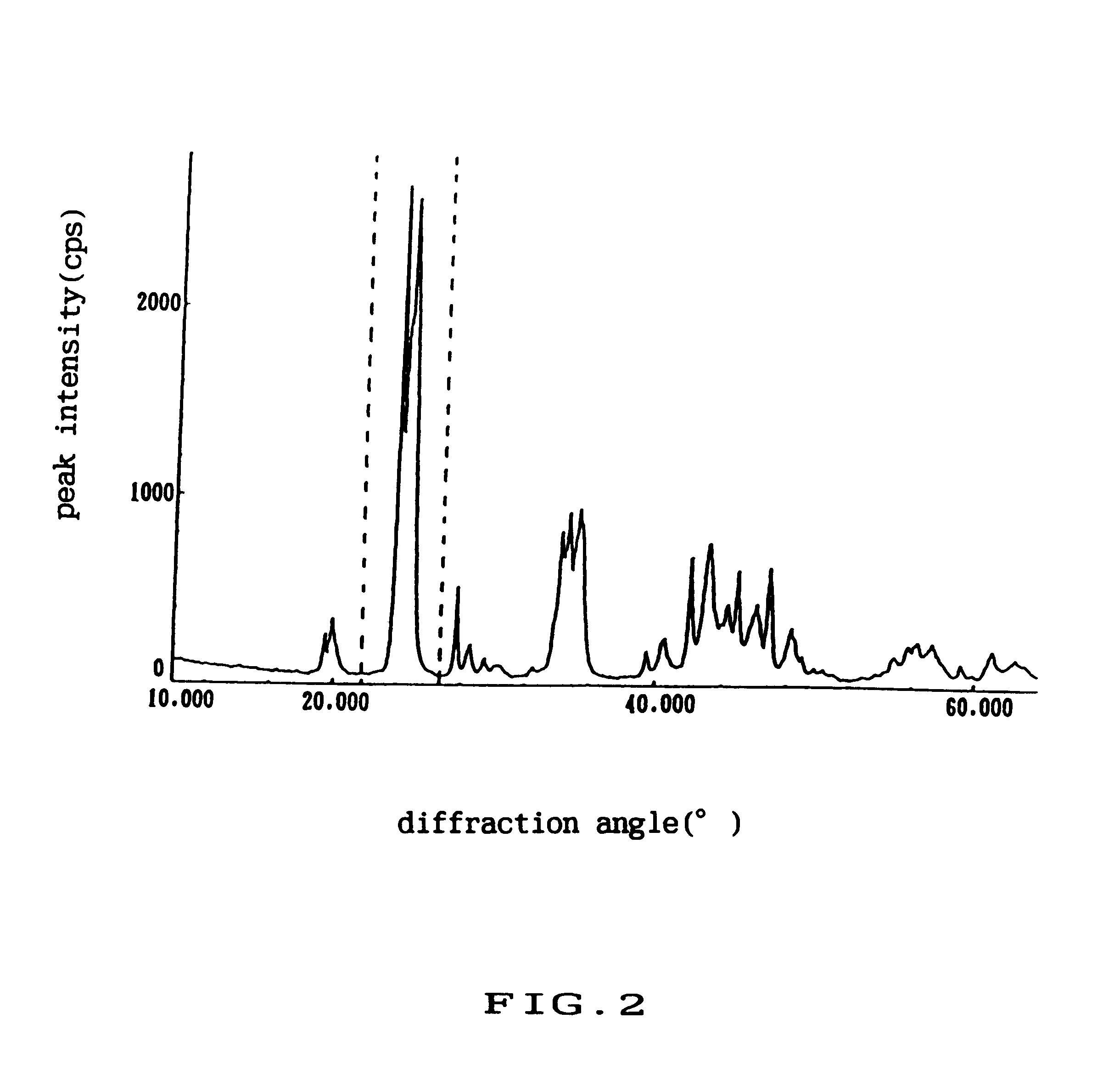
According to the present invention, at least one kind of alkaline earth metal carbonate is distributed locally in a mixed crystal or solid solution of alkaline earth metal carbonate so that the emitter material for a CRT can be provided with enough life characteristics even when used with an emission current of more than 2A / cm.sup.2, for example, 3A / cm.sup.2. Moreover, the emitter material of the present invention permits a larger screen size, high brightness and high resolution. The emission slump can be inhibited by making the average particle size of dispersed alkaline earth metal carbonate be within the above-mentioned range. The emission slump herein represents the phenomenon where the emission current gradually decreases during the time of a few seconds to a few minutes at the beginning of electron emission until the emission current stabilization. In addition, an emitter material for a CRT that can realize these characteristics has an X-ray diffraction pattern for alkaline earth metal carbonate having two peaks or more in the interplanar spacing ranging from 0.33 nm to 0.40 nm.
In the case where crystalline particles of alkaline earth metal carbonate are synthesized by adding at least two kinds of alkaline earth metal nitrate aqueous solution into an aqueous solution comprising carbonic acid ions individually at different addition rates, at least one kind of alkaline earth metal carbonate is separated in a crystalline particle of carbonate so that the emitter material for a CRT can be provided with enough life characteristics even when operated with an emission current of more than 2A / cm.sup.2, for example, 3A / cm.sup.2. Moreover, the emitter material of the present invention permits a larger screen size, high brightness and high resolution.
In any of above mentioned cases, in the case where the elements of alkaline earth metal carbonate crystalline particle comprises barium carbonate and strontium carbonate or comprises barium carbonate, strontium carbonate and calcium carbonate, the good emission characteristics can be obtained and also a larger screen size , higher brightness and higher resolution of the CRT can be realized.
Moreover, in any of above mentioned cases, the good emission characteristics can be obtained and a larger screen size, high brightness and a high resolution can be realized by adding at least one selected from the group consisting of rare earth metal, rare earth metal oxide and rare earth metal carbonate. Furthermore, ytrrium atoms can be added in an amount of 550-950 ppm with respect to the number of atoms of alkaline earth metal making an emitter material by the coprecipitation method. As compared with the case where no yttrium atoms are added, the thermal decomposition temperature decreased by approximately 100.degree. C., thus reducing the thermal decomposition time as well as the manufacturing cost.

Problems solved by technology

However, if the conventional emitter materials for CRTs are used at the current density above 2A / cm.sup.2, a sufficient lifetime cannot be maintained.
Thus, the conventional emitter materials cannot be employed for a CRT that is aiming at a larger screen size, higher brightness and higher resolution.

Method used

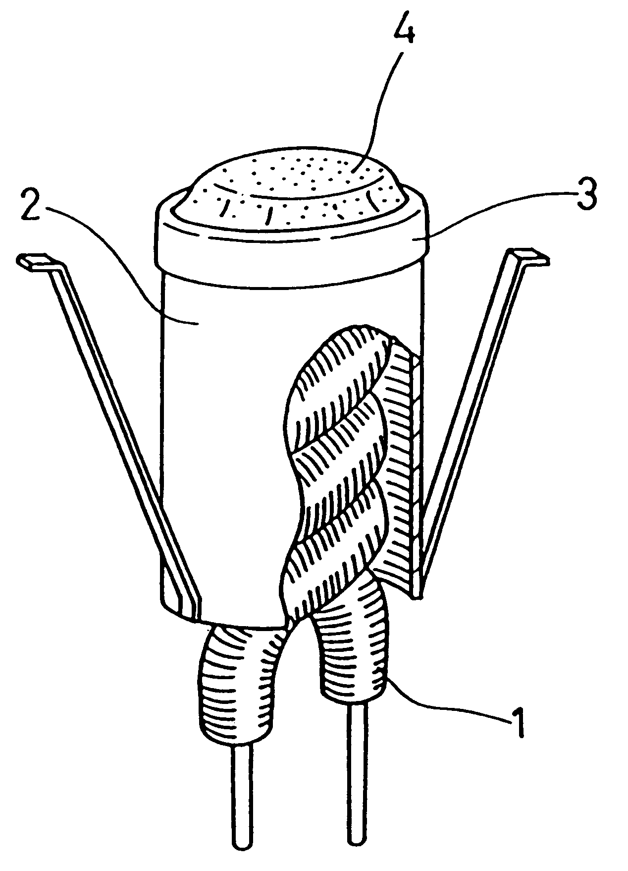
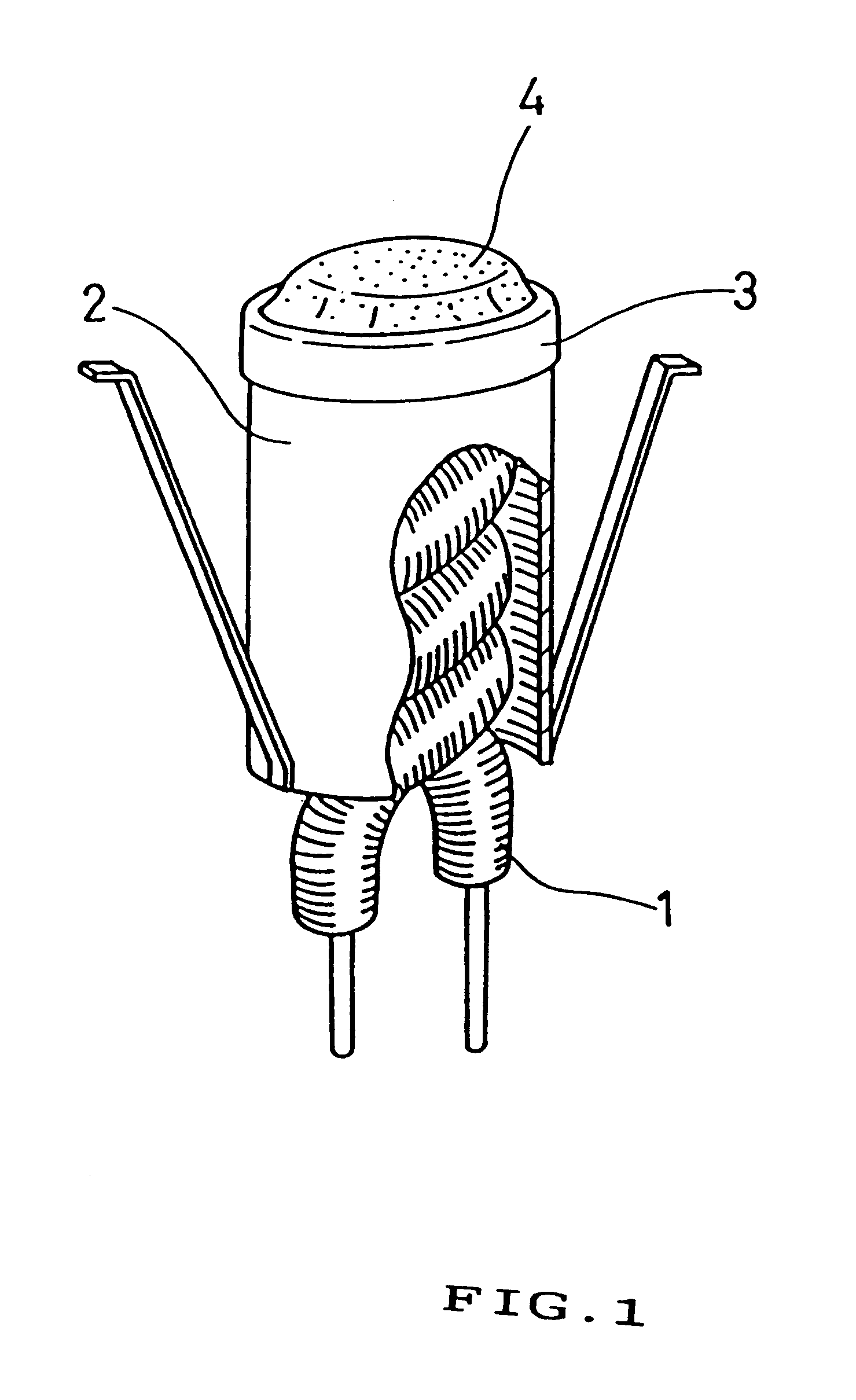

Image

  • Emitter material for cathode ray tube having at least one alkaline earth metal carbonate dispersed or concentrated in a mixed crystal or solid solution
  • Emitter material for cathode ray tube having at least one alkaline earth metal carbonate dispersed or concentrated in a mixed crystal or solid solution
  • Emitter material for cathode ray tube having at least one alkaline earth metal carbonate dispersed or concentrated in a mixed crystal or solid solution

Examples


first embodiment

Referring now to figures, there are illustrated the present invention.

Binary carbonate, which was synthesized by the sodium carbonate precipitation method and shows the X-ray diffraction pattern as shown in FIG. 18, and BaCO.sub.3 were mixed at the weight ratio of 2:1, thus making a mixed carbonate A. Then, the above mentioned binary carbonate and SrCO.sub.3 were mixed with the weight ratio of 2:1, thus making a mixed carbonate B. Further, the above mentioned binary carbonate, BaCO.sub.3 and SrCO.sub.3 were mixed at the weight ratio of 4:1:1, thus making a mixed carbonate C.

The above mentioned binary carbonate was obtained through the following steps of: dissolving 5 kilograms of barium nitrate and 4 kilograms of strontium nitrate in 100 liters of hot water at a temperature of 80.degree. C. (This aqueous solution is designated as "solution W" for ease of reference.); dissolving 8 kilograms of sodium carbonate in hot water at a temperature of 80.degree. C. (This aqueous solution is d...

example 2

Referring now to the figures, there is illustrated the second embodiment of the present invention.

Ternary carbonate, which was synthesized by the sodium carbonate precipitation method and shows the X-ray diffraction pattern as shown in FIG. 19, and BaCO.sub.3 were mixed at a weight ratio of 2:1, thus making a mixed carbonate D.

The above mentioned ternary carbonate was obtained through the following steps of: dissolving 4.8 kilograms of barium nitrate and 3.8 kilograms of strontium nitrate and 0.75 kilograms of calcium nitrate in 100 liter of hot water at a temperature of 80.degree. C. (This aqueous solution is designated "solution Y" for ease of reference.); dissolving 8 kilograms of sodium carbonate in 35 liter of hot water at a temperature of 80.degree. C. (This aqueous solution is designated "solution Z" for ease of reference); stirring the solution Y and keeping it at the temperature of 80.degree. C.; adding the solution Z into the solution Y at the adding rate of 2 liters per o...

example 3

Referring now to figures, there is illustrated the third embodiment of the present invention.

Barium nitrate, strontium nitrate and sodium carbonate were respectively dissolved into pure water to make barium nitrate aqueous solution (K), strontium nitrate aqueous solution (L) and sodium carbonate aqueous solution (N). All of the concentrations of the above mentioned K, L and N were controlled to be 0.5 mol / liter. Then, barium nitrate aqueous solution (K) and strontium nitrate aqueous solution (L) at temperatures of 80.degree. C. were added in an amount of 30 liters each into 60 liters of sodium carbonate aqueous solution (N) that was heated to 80.degree. C., at different adding rates, thus making a precipitate of alkaline earth metal carbonate. In this example, the synthesizing reaction was carried out at two types of adding rates (K and L) as shown in FIG. 9 and FIG. 10. As is apparent from FIG. 9, in the first type of adding rate, the adding rate of K was constant and the adding ra...


PUM


Abstract

An emitter material for a CRT comprises mixed crystal or solid solution of at least two kinds of alkaline earth metal carbonate, wherein at least one alkaline earth metal carbonate is dispersed or separated in the mixed crystal or solid solution. The alkaline earth metal carbonate, which is an emitter material for the CRT, is coated onto the base metal and thermally decomposed in a vacuum to from an emitter of an alkaline earth metal. This emitter, which is proper for a larger screen size, high brightness and high resolution CRT, can be provided with enough life characteristics even under the operating condition of the emission current density of 2A / cm2.

Description

This invention relates to an emitter material for a cathode ray tube (CRT) used in television, a display or the like.Conventionally, alkaline earth metal carbonate for a cathode ray tube has been synthesized by adding sodium carbonate aqueous solution or ammonium carbonate aqueous solution into a binary mixed aqueous solution comprising barium nitrate and strontium nitrate, or a ternary mixed aqueous solution comprising above-mentioned binary mixed aqueous solution and calcium nitrate, at a predetermined addition rate and reacting therewith to thus precipitate binary (Ba, Sr) carbonate or ternary (Ba, Sr, Ca) carbonate. The method includes, for example, a sodium carbonate precipitating method. This sodium carbonate precipitating method represents synthesizing alkaline earth metal carbonate by adding a sodium carbonate aqueous solution as a precipitant into a binary mixed nitrate aqueous solution comprising barium nitrate and strontium nitrate or a ternary mixed nitrate aqueous solut...

Claims


Application Information

Patent Timeline
Patent Type & Authority Patents(United States)
IPC IPC(8): H01J1/142H01J1/13H01J1/316H01J9/04H01J29/04
CPCH01J1/142H01J9/042H01J1/316H01J1/14
Inventor OZAWA, TETSUROHAYASHIDA, YOSHIKISAKURAI, HIROSHI
Owner PANASONIC CORP
Learn More