Apparatus and process for electrodialysis of salts

a technology of apparatus and process, applied in the direction of fluid pressure measurement, liquid/fluent solid measurement, peptide, etc., can solve the problems of reducing current throughput, high capital and operating costs, and feed salts containing a significant amount of divalent metal ions, calcium and magnesium,

Inactive Publication Date: 2001-05-01
ARCHER DANIELS MIDLAND CO
View PDF1 Cites 11 Cited by
  • Summary
  • Abstract
  • Description
  • Claims
  • Application Information

AI Technical Summary

Problems solved by technology

Such cell arrangements convert the salt to an acid and a base at a higher current efficiency, as compared to the conversion of the two-compartment cells shown in FIGS. 1(a) and 1(b), but it is also at higher capital and operating costs.
Despite the usual filtration / ultrafiltration and carbon treatment steps, a major problem in using the electrodialysis cells in the water splitting applications, is that the feed salt contains a significant amount of divalent metal ions, particularly calcium and magnesium.
The precipitation of these ions inside the base loop plugs the cells, and damages the membranes thereby decreasing the current throughput and, in the extreme, causing a mechanical failure resulting from an overheating and, perhaps, a meltdown.
A problem with this approach is that the pH of the feed stream has to be raised to >9 through an addition of a base material.
The added base would then have to be recovered in the electrodialysis unit at an added cost in terms of the capital cost of the membrane area and electrical power consumption.
However, a problem is that the flue gas, which is derived from the combustion of fossil fuels, contains flyash derived impurities, usually including calcium and magnesium compounds and, possibly, corrosion products (iron) from the duct work through which the flue gas passes.
The presence of these impurities make the processing of the bisulfite stream in the water splitter rather difficult, if not impossible.
While effective in reducing or eliminating the precipitate formation at the bipolar membrane surface, the co-pending application does not address either the production of concentrated alkaline solutions or the production of multivalent acids.

Method used


Image

  • Apparatus and process for electrodialysis of salts
  • Apparatus and process for electrodialysis of salts
  • Apparatus and process for electrodialysis of salts

Examples


example 1

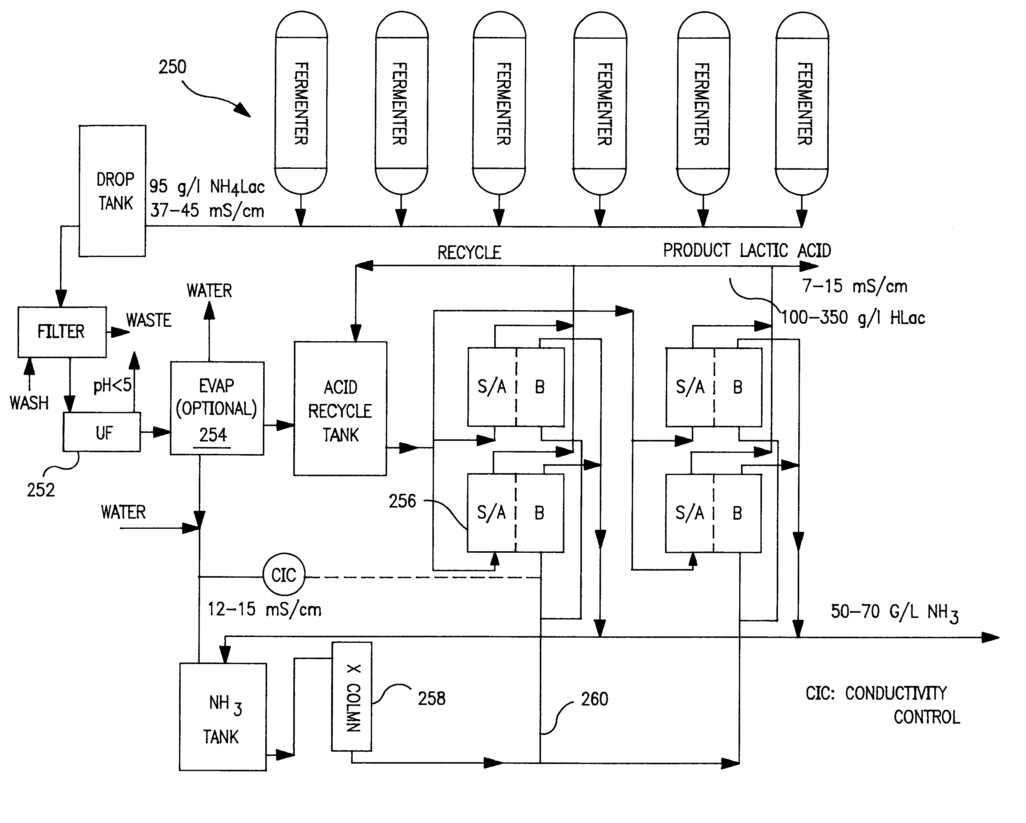
The pilot cell was assembled with AQ bipolar membranes and CMV cation membranes. One hundred and six liters of ultrafiltered ammonium lactate solution was charged into the acid recycle tank 204 (FIG. 7). The conversion to acid was monitored through conductivity and pH measurements. The base loop 198 did not have an ion exchange column 206. The base tank 202 was initially charged with dilute ammonium hydroxide solution and as the ED process operated, the product ammonia solution overflowed from the base recycle tank 202. Small amounts of dilute NaCl solution were added to the base loop 198 to improve its conductivity. The process was deemed complete when the conductivity fell to around about 7 mS / cm.

The trial lasted approximately 15 hours. Samples of acid and base were collected and analyzed for lactic, ammonia and divalent metals. The results were as follows:

The trial produced 96 liters of product at a concentration of 87 gm / l. Ammonia removal was about 87%. As can be seen, the pH i...

example 2

The Example 1 was repeated after replacing the CMV cation membranes with AQ cation membranes. A hundred six and one half liters of the ammonium lactate feed were processed over 817 minutes to yield a product acid containing 1.58 gm / l NH.sub.3 at an average current input of 33.2 A (66.4 A / ft.sup.2). Ammonia removal was about 92%. The lactic loss via diffusion to the ammonia loop was about 2.8%. The overall current efficiency for the process was about 68%. However, metals analysis showed that the retention of the divalent metals was lower than for CMV; about 42% for magnesium, and about 37% for calcium. Therefore, the ammonia solution from the test had higher levels of dissolved metals: about 10-19 ppm calcium and 5-31 ppm magnesium. At the end of the experiment, the AQ cations were somewhat mottled in appearance, indicating possible fouling by the divalent cations.

example 3

Eight batches of ammonium lactate feed containing 70-92 gm / I lactate, with an initial conductivity of 28 to 42 mS / cm, were processed in the pilot cell. The cell contained AQ bipolar membranes, and CMV cation membranes that were used in Example 1. The input feed streams were subjected to ultrafiltration (200,000 Daltons cutoff). There was no ion exchange column 206 in the base loop 198. Ammonium hydroxide was at a concentration of 30-66 g / l and conductivity of 11 to 32 mS / cm was generated in the base loop 198. A diffusion of a small amount of lactic anion into the base loop 198 provided the requisite conductivity in the loop. No water or salt solution addition was made during these operations. The batches were of varying size and lasted from 6.35 to 40.3 hours. Each batch was terminated when the acid loop conductivity had decreased to about 7-10 mS / cm. During the batches, the ammonium ion concentration in the acid loop 196 dropped from 7-12 gm / l to 1.1-3.6 gm / l.

The total cell voltage...


PUM

PropertyMeasurementUnit
pKaaaaaaaaaaa
voltageaaaaaaaaaa
molecular weightaaaaaaaaaa

Abstract

An apparatus and process produces salts by an electrodialysis operation. The basic electrodialysis apparatus is a cell having a number of compartments separated by membranes. A DC source is connected to drive a current through a feed stream passing through the cell which splits the salt stream into an acid and a base. The incoming feed may be nanofiltered to remove divalent metal. The base loop may be in communication with an ion exchange column packed with a material that removes multivalent cations. Depending upon the material being processed and the desired end result either or both the nanofiltration and the ion exchanged column may be used in the apparatus.

Description

This invention relates to apparatus and processes for electrodialysis of salts and more particularly to apparatus and processes that incorporate at least one of two distinct features: a nanofiltration unit combined with an electrodialysis unit and an ion exchange column connected to and in communication with the base loop of an electrodialysis cell.This electrodialysis apparatus can be used in a number of large scale process applications. Specifically, it may be used for the recovery of lactic acid from fermentation derived ammonium lactate in a two compartment cation cell. There may be either a nanofilter or an ion exchange column (or both) in communication with the base loop of the cation cell. The column contains a weak acid cation exchange resin.For more information on the background of the inventive structure, reference may be made to my co-pending applications shaving the following identifications: Process for the Recovery of Organic Acids and Ammonia from Their Salts, Ser. No...

Claims


Application Information

Patent Timeline
Patent Type & Authority Patents(United States)
IPC IPC(8): B01D61/44B01D61/42B01D61/58B01D61/52C01D1/00C01D5/00C01D5/14C01C1/02C01D1/40C01D7/00C01D7/34C01C1/00C07C51/02
CPCB01D61/44B01D61/445B01D61/52B01D61/58C01C1/02C01D1/40C01D5/14C01D7/34C07C51/02C12P7/40C12P7/54C12P7/56C25B1/16C07C53/08C07C53/02C07C59/08B01D61/027B01D61/145B01D61/422C02F1/4693
Inventor MANI, K. N.
Owner ARCHER DANIELS MIDLAND CO
Why Eureka
Try Eureka