Hybrid catalyst heating system with water removal for enhanced emissions control

Inactive Publication Date: 2001-05-22
LYNNTECH POWER SYST
View PDF28 Cites 115 Cited by
  • Summary
  • Abstract
  • Description
  • Claims
  • Application Information

AI Technical Summary

Problems solved by technology

All of these methods have drawbacks and limitations.
Placing the catalytic converter almost immediately adjacent to the engine is not desirable because of the tendency to overheat the catalyst with resulting accelerated degradation of the catalyst.
Thermal insulation is also not a desirable option because of the same problems, especially during operation at maximum operating temperature ranges.
Limitations on the equipment and process, however, affect the utility of this method.
The primary limitation on electrical preheating is the electrical energy required by the heater.
The typical car battery is not a practical power source to supply the electrical power because the electrical load on the vehicle battery during the period required may exceed the rated battery output.
In any event, the load placed on a typical 12 volt vehicle battery will shorten the lifetime of the battery.
Also, there is a measurable delay between the time the operator of the vehicle places the ignition switch in the "on" position and the time the heater brings the catalyst to light-off temperature.
Typically, in the interval between start up and light-off, the exhaust stream is oxygen deficient.
Even when using a secondary air flow to overcome oxygen deficiency, the secondary air flow must be closely controlled to avoid an excess of oxygen, in which case the catalytic converter is less effective in reducing NO.sub.x.
However, it should be noted

Method used


Image

  • Hybrid catalyst heating system with water removal for enhanced emissions control
  • Hybrid catalyst heating system with water removal for enhanced emissions control
  • Hybrid catalyst heating system with water removal for enhanced emissions control

Examples


Example

EXAMPLE #2

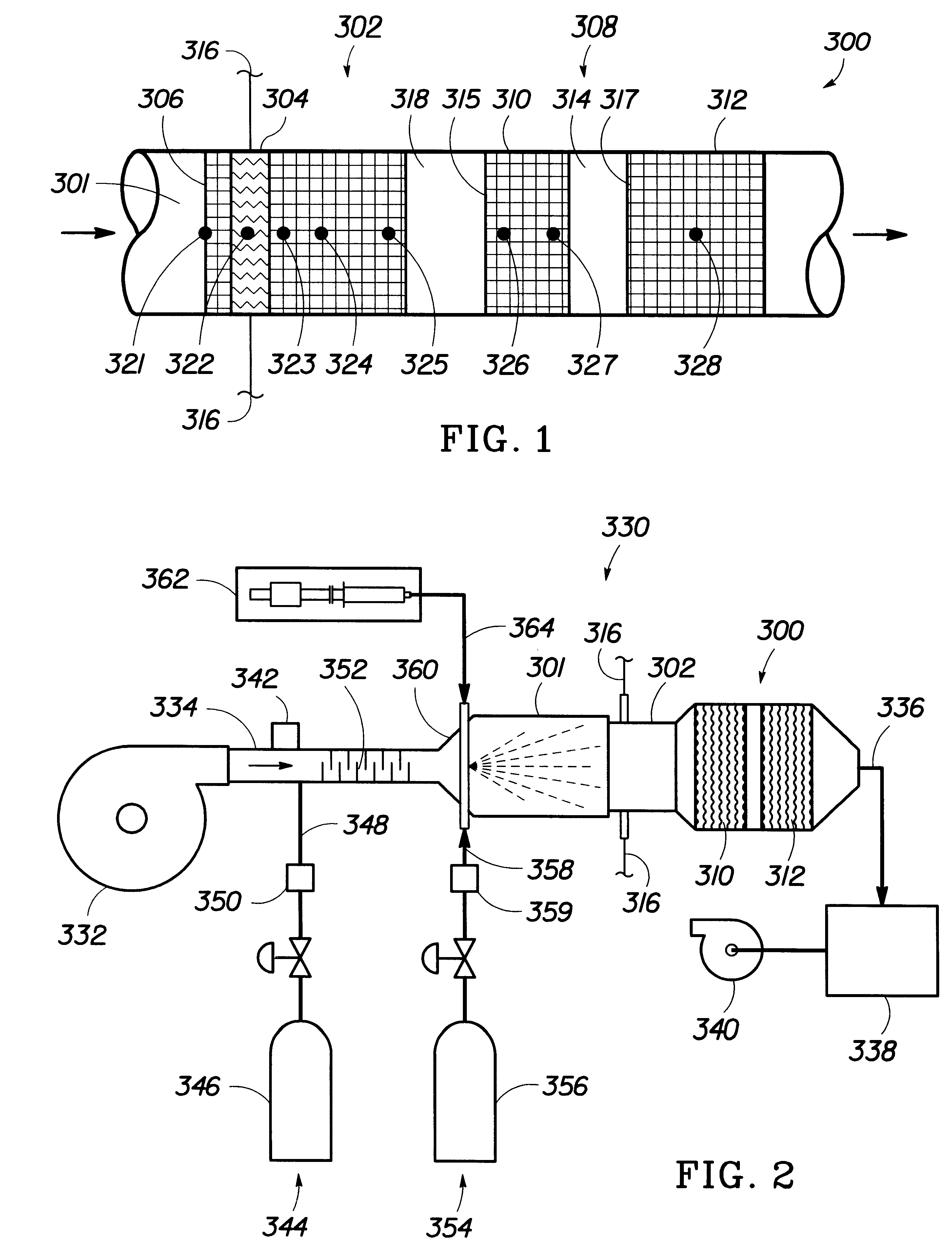
The experimental setup 330 of FIG. 2 was used for the introduction of hydrogen and air to a wet catalytic converter 300. About 2 milliliters per minute of water was applied to the converter 300 at room temperature over a period of about 10 minutes through the liquid injection subsystem and allowed to soak for a period of about 10 minutes to simulate water that condenses in an automotive catalytic converter as the system cools. The blower 332 then provided air through the catalytic converter 300 at a rate of about 325 liters per minute (lpm) with about 6 vol % hydrogen. FIGS. 8(a-d) are graphs of the catalyst temperature over time with introduction of hydrogen and air to a wet catalyst along with no electrical heating, electrical heating from room temperature to 50.degree. C., electrical heating from room temperature to 100.degree. C., electrical heating from room temperature to 150.degree. C.

In the graphs, the temperature profile given by each thermocouple is labeled by th...

Example

EXAMPLE #3

The experimental setup 330 of FIG. 2 was used for the introduction of methanol and air to the catalytic converter 300. The blower 332 then provided air through the catalytic converter 300 at a rate of about 325 liters per minute (lpm) for a sufficient period of time to achieve a steady state temperature of 100.degree. C. throughout the entire catalytic converter. FIGS. 9(a-d) are graphs of the catalyst temperature over time with introduction of methanol at flow rates of 20 milliliters per minute (mlpm), 30 mlpm, 40 mlpm and 50 mlpm, respectively. The front thermocouple 321 is initially cooled by the flow of methanol and air. It is also apparent that the higher methanol flow rates provides more rapid heating.

Example

The procedure of Example 3 was repeated, but at an initial steady state temperature of 150.degree. C. FIGS. 10(a-d) are graphs of catalyst temperature over time with introduction of methanol at flow rates of 20 milliliters per minute (mlpm), 30 mlpm, 40 mlpm and 50 mlpm, respectively. Comparing FIGS. 10(a-d) with FIGS. 9(a-d), it is shown that a higher initial catalyst temperature allows the chemical heating to proceed at a much faster rate than at low initial catalyst temperatures.


PUM

PropertyMeasurementUnit
Angleaaaaaaaaaa
Angleaaaaaaaaaa
Angleaaaaaaaaaa

Abstract

The present invention provides a method and apparatus for heating a catalytic converter at least to a light off temperature. In accordance with the invention, the catalytic converter may be heated using a novel monolith construction, electrical heating, catalytic combination of a fuel and oxygen or combinations of these methods. Heating or thermally conditioning a catalyst in accordance with the invention rapidly brings the catalyst up to the light off temperature for the efficient conversion of pollutant gases, such as unacceptable emissions emanating from an internal combustion engine, into water, carbon dioxide and other acceptable emissions. In particular, the invention provides efficient heating of the catalytic converter despite the potential presence of water on the catalyst during startup.

Description

1. Field of the InventionThe present invention relates generally to the field of catalysis for the reduction of emissions from internal combustion engines. More particularly, the present invention relates to a method and apparatus for rapidly heating a catalytic converter to operating temperatures.2. Background of the Related ArtCatalytic converters are commonly used to reduce unwanted emissions through catalytic combination of the emissions with oxygen from the air. Catalytic combination, often referred to as catalytic combustion, is a flameless process in which mixtures of emissions (or fuel) and air (or oxygen) are passed over a catalyst at a temperature high enough to favor total oxidation of the emissions (or of the fuel). The reaction occurs at the catalyst surface resulting in liberation of energy and production of reaction products. For organic fuels, the reaction products are primarily carbon dioxide and water.The control and suppression of unwanted emissions created by the...

Claims


Application Information

Patent Timeline
IPC IPC(8): B01D53/94F01N3/22F01N3/20F01N7/00F01N7/02F01N13/02
CPCB01D53/944F01N3/2013F01N3/22F01N13/009F01N2610/03F01N2610/04F01N2610/08Y02T10/26Y02T10/22Y02T10/12
Inventor MURPHY, OLIVER J.KUKREJA, RAJESH T.
Owner LYNNTECH POWER SYST
Why Eureka
Try Eureka