Fluid metering roll and method of making the same

a technology of fluid metering and rolling pin, which is applied in the direction of portable power-driven tools, applications, and ways, etc., can solve the problems of rolling deflection, premature bearing wear, and difficulty in dynamic balan

Inactive Publication Date: 2001-06-05
PAMARCO
View PDF9 Cites 16 Cited by
  • Summary
  • Abstract
  • Description
  • Claims
  • Application Information

AI Technical Summary

Problems solved by technology

Anilox rolls as heretofore known incorporate many characteristics which are undesirable.
As will be set out more fully hereinafter, drawbacks of conventional anilox rolls include high weight and inertia, characteristics which result in roll deflection, premature bearing wear, difficulty of dynamic balance, and mandated high driving forces.
A further drawback of conventional anilox rolls, which typically may require use in caustic environments, resides in their low resistance to corrosion.
Despite the various sealants employed in ceramic, conventional anilox rolls, and notwithstanding the nature of the electroplated layers used in fabricating metallic anilox rolls, exposure to corrosive reagents, and necessity for frequent cleaning of the anilox roll surfaces, rapidly compromises the roll, resulting in the necessity of reprocessing.
In fact, slight imbalances are governing factors in the speeds at which the roll may be employed, and hence, the speed of the printing or other process.

Method used


Image

  • Fluid metering roll and method of making the same
  • Fluid metering roll and method of making the same
  • Fluid metering roll and method of making the same

Examples


example 2

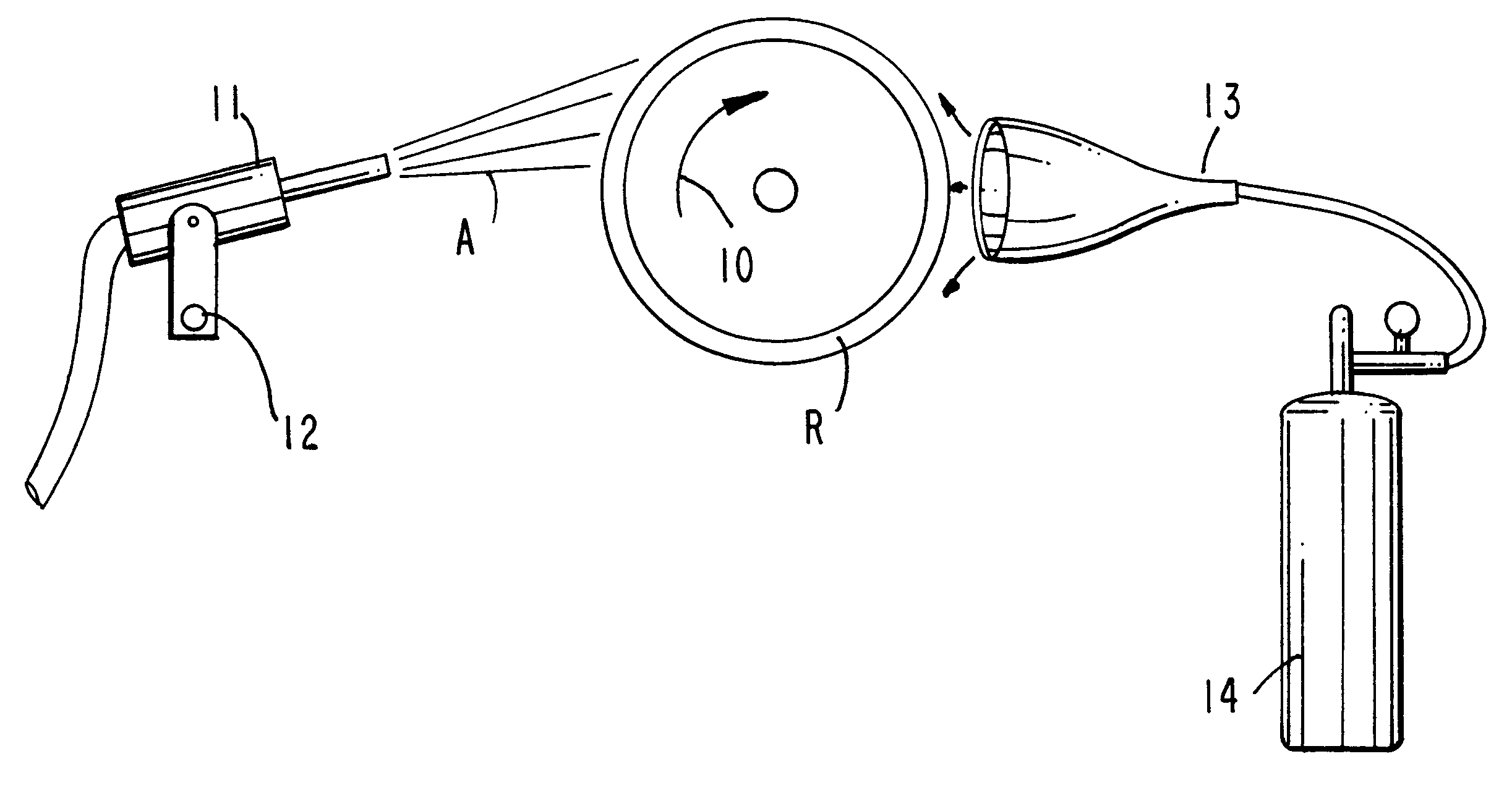
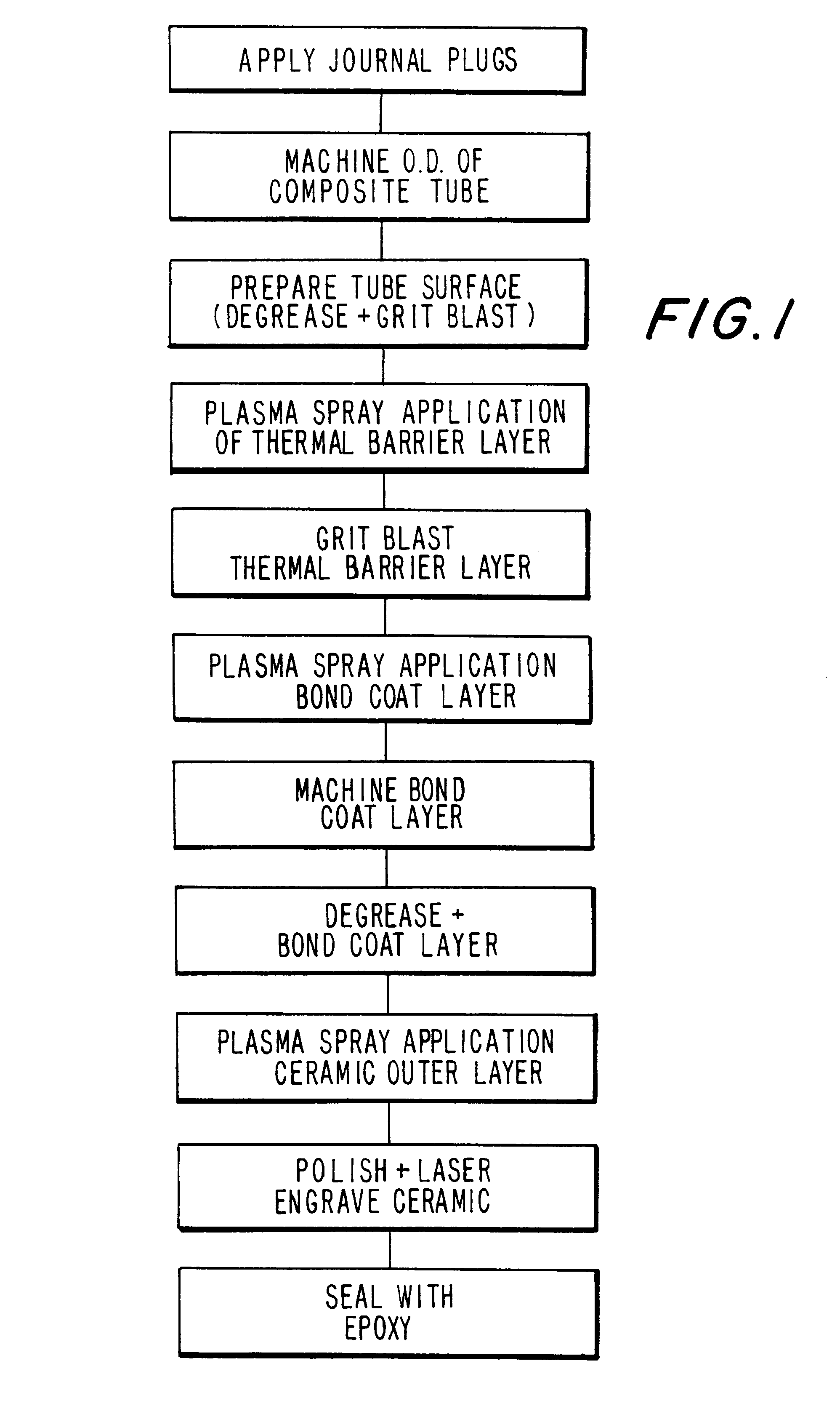
A carbon fiber composite roll of the characteristics noted above and dimensioned as before and formed with a zinc thermal barrier layer as previously described was overcoated with a bond coat comprised of nickel and chromium (80 / 20) by weight. A bond coat of 0.005 inches was formed utilizing Metco 9MB gun, 9MP power feeder nozzle GH; pick up shaft A; powerport 2 operating at electrical parameter of 70 volts 500 amps spray rate 10 pounds per hour. Gas pressure employed was 100 parts argon to 50 parts hydrogen, argon at 80 SCFH and hydrogen at 15 SCFH. Spray distance was 4.5 inches, surface speed of the roll was 400 surface feet per minute, the roll rotating 6 rotations per 1" traverse of the applicator gun.

The bond coat thus formed was machined, degreased, plasma sprayed as before.

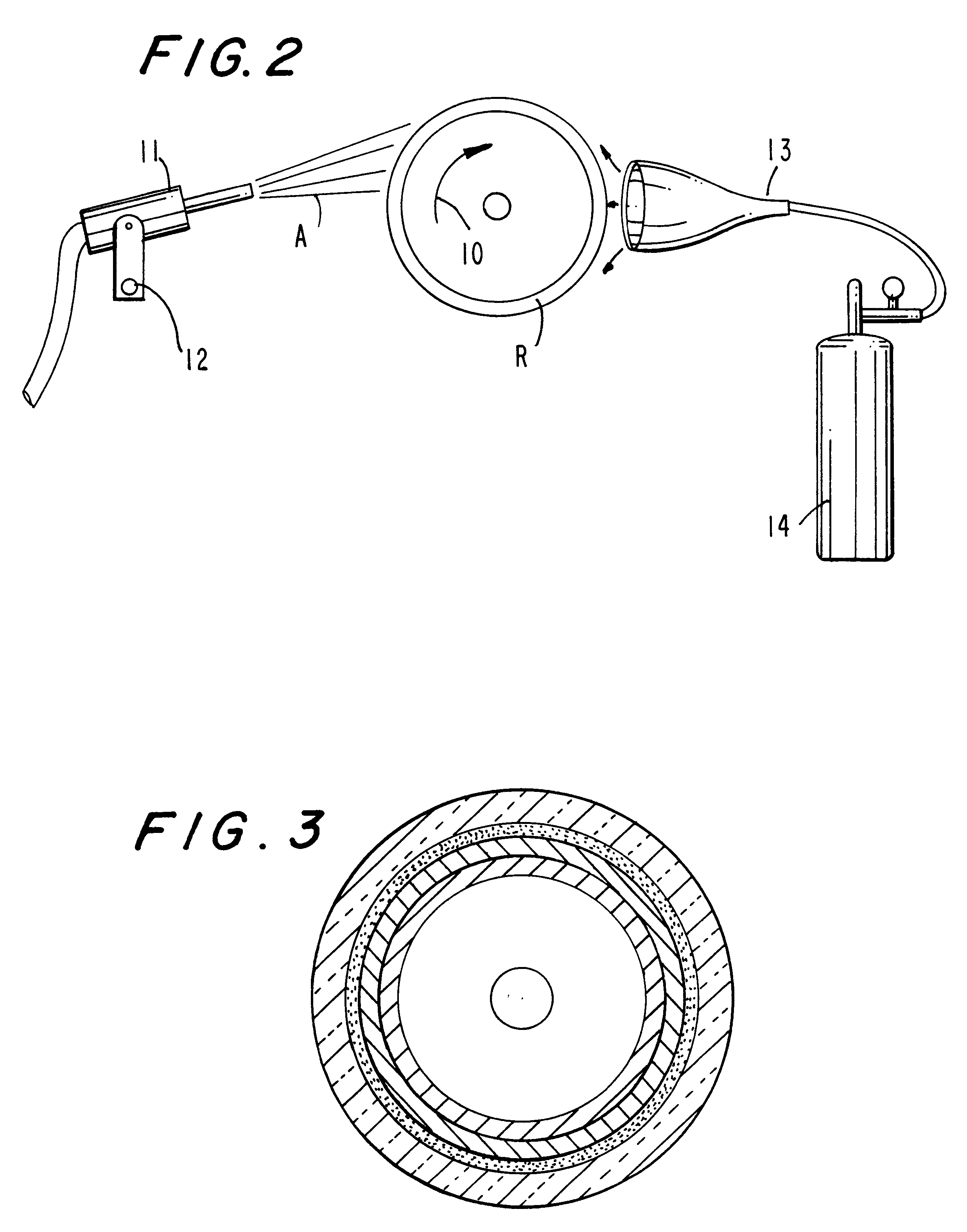
While it is preferred to employ both a thermal barrier layer and a bond coat layer prior to application of the ceramic layer, it is feasible in some instances to apply the ceramic layer directly over a ther...


PUM

PropertyMeasurementUnit
temperatureaaaaaaaaaa
weightaaaaaaaaaa
weightaaaaaaaaaa

Abstract

A fluid metering roll such as an anilox roll is comprised of a tubular carbon fiber composition core having one or more metallic layers intervening between the core and a surface layer comprised of ceramic, the ceramic having outwardly opening fluid metering cells. The method of forming the roll includes steps of thermal spray applying one or more layers comprised of metal over the roll surface the layers intervening between the roll and an external ceramic coating. Characterizing features of the application method reside in each of the thermal spray applied layers being directed toward the core at a negative rake angle of from about 11½ to about 13½ and preferably 12½°, the core and layers which receive the thermal spray being simultaneously cooled to about 110° Centigrade or less during application of the thermal spray. The method and article are further characterized in that the coefficient of thermal expansion of the layers intervening between the core and the outermost ceramic layer form a progression whereby the intermediate layers have thermal characteristics which progressively become smaller in the outward direction.

Description

The present invention is directed to a fluid metering roll and to a novel method of manufacturing same. More particularly the invention is directed to an anilox roll characterized in that the roll is comprised of a carbon fiber composite core having an exterior ceramic surface formed with outward opening metering cells.It is the objective of anilox rolls to pick up liquid, typically ink, from an ink source and to deposit on a subsequent printing roller or the like, discrete increments of ink, the quantity deposited by each cell being controlled within precise tolerances across the entire surface of the printing roller, this result being effected by the anilox roller having a multiplicity of closely-spaced, i.e., up to 1,000 or more, cells per lineal inch, the cells having virtually identical volumetric capacities.PRIOR ARTConventional anilox rolls are manufactured from either steel or aluminum cores. The external surfaces of the cores are typically mechanically engraved with the des...

Claims


Application Information

Patent Timeline
Patent Type & Authority Patents(United States)
IPC IPC(8): B41N7/00C23C4/02
CPCB41N7/00C23C4/02B41N2207/02Y10T29/4956B41N2207/10Y10T29/49563B41N2207/04
Inventor HYCNER, STANLEY H.
Owner PAMARCO
Why Eureka
Try Eureka