Eureka AIR delivers breakthrough ideas for toughest innovation challenges, trusted by R&D personnel around the world.

Optically active monomer, liquid crystal polymer, and optical element

a liquid crystal polymer and monomer technology, applied in the field of optically active monomers, can solve the problems of hindering light-weighting and thinning of liquid crystal displays, difficult to increase luminance and decrease the electric power consumed by liquid crystal display devices, and the thickness of optical elements, so as to improve the efficiency of light utilization, reduce surface reflection loss, and improve the effect of light utilization efficiency

Inactive Publication Date: 2001-06-19
NITTO DENKO CORP
View PDF6 Cites 10 Cited by
  • Summary
  • Abstract
  • Description
  • Claims
  • Application Information

AI Technical Summary

Benefits of technology

Also, the wavelength region showing the circular dichroism can be controlled by mixing two or more kinds of liquid crystal polymers each having a different wavelength region showing the circular dichroism. Accordingly, as shown in the example described below, an optical element showing a circular dichroism to a light of a visible light region can be easily obtained.
In laminating, it is preferable to attempt reducing surface reflection loss in each boundary using an adhesive or the like.
In addition, in the above-described combination, the point of combining the liquid crystal polymer layers each reflecting the circularly polarized light to a same direction aims at preventing each reflected circularly polarized light from becoming a different polarization state by making uniform the phase state of the circularly polarized light reflected at each layer and also improving the efficiency of re-utilizing the reflected circularly polarized lights in the case of re-utilizing the reflected circularly polarized lights via the reflection layers, etc.
The optical element of the present invention showing the circular dichroism separates an incident light into a right circularly polarized light and a left circularly polarized light based on the circular dichroism thereof and supplies as a transmitted light and a reflected light, and can improve the utilization efficiency of the light by re-utilizing the reflected light via the reflection layer, etc. Thus, the optical element of the present invention can be preferably used as an illuminator such as a polarizing plate, a back light, etc., in various apparatus such as a direct-vision type liquid crystal display device, etc.
The retardation layer for converting the circularly polarized light to a linearly polarized light is for changing the phase of the circularly polarized light from the optical element and converting to a state having many linearly polarized light components. By converting to the state having many linearly polarized light components, a bright display by the direct incident to a liquid crystal cell and a bright display via the incident to a polarizing plate formed at a liquid crystal cell become possible.
The retardation layer can be formed as a single layer or two or more layers. In the case of the retardation layer comprising a single layer, the retardation layer showing the small wavelength dispersion of double refraction is preferred because in this case, the homogeneity of the polarized state of each wavelength can be obtained. On the other hand, the lamination of the retardation layers is effective for the improvement of the wavelength characteristics in a wavelength region and the combination thereof may be properly determined according to the wavelength region, etc.

Problems solved by technology

A polarizing film prepared by adsorbing a dichromatic dye, etc., to a stretched film, such as a stretched polyvinyl alcohol film, etc., cannot be effectively used because at least 50% of an incident light is absorbed, and thus it is difficult to increase a luminance and decrease a consumed electric power of a liquid crystal display device, etc.
However, in the former low molecular weight material, because substrates are used, the optical element becomes thick and heavy and there is a problem of hindering light-weighting and thinning of the liquid crystal display.
Also, there is a problem that the orientation state of the liquid crystal, for example, a pitch thereof is liable to be changed by the change of temperature, etc.
On the other hand, in the case of using the latter liquid crystal polymer, it is difficult to obtain a solid material such as a film of a good oriented state as a low molecular weight material, a long time such as several hours, etc., is required for the orientation treatment, the glass transition temperature thereof is low, or the durability is insufficient, resulting in poor practical use.
Thus, in any cases, it is difficult to obtain an optical element having a circular dichroism in a solid state, in particular, the optical element for visible light.
For the purpose of improving the solid state, various attempts of combining monomers, in particular changing monomers having a cholesteric phase-imparting property have been made, but at present the problems of being poor in liquid crystal orienting property and heat resistance have not yet been solved.

Method used


Image

  • Optically active monomer, liquid crystal polymer, and optical element
  • Optically active monomer, liquid crystal polymer, and optical element
  • Optically active monomer, liquid crystal polymer, and optical element

Examples


example 2

(d1) ##STR13##

In 16.5 ml of tetrahydrofuran were dissolved 0.168 g (0.31 mmol) of the optically active monomer represented by the formula (b1) and 1.56 g (3.78 mmols) of a monomer represented by the above-described formula (d1) by heating in a reaction vessel, after stabilizing the reaction system at a temperature of from 55 to 60.degree. C., the inside atmosphere was replaced with a nitrogen gas, 0.5 ml of a tetrahydrofuran solution having dissolved therein 0.5 g of azobisisobutyronitrile was added dropwise to the solution in the absence of oxygen, and the polymerization was carried out for 3 hours. The reaction mixture obtained was gradually poured in 150 ml of diethyl ether with stirring to obtain precipitates of a white polymer and by collecting the precipitates by filtration and drying, a copolymer was obtained (yield 58%). The glass transition temperature of the copolymer was 90.degree. C. and the copolymer showed a cholesteric structure having an isotropic phase transition te...

example 3

According to Example 2, a copolymer having a glass transition temperature of 92.degree. C. and showing a cholesteric structure having isotropic phase transition temperature of 275.degree. C. was obtained using 0.15 g (0.28 mmol) of the optically active monomer represented by the formula (b1) and 1.64 g (3.98 mmols) of the monomer rrepresented by the above-described formula (d1).

example 4

According to Example 2, a copolymer having a glass transition temperature of 95.degree. C. and showing a cholesteric structure having isotropic phase transition temperature of 282.degree. C. was obtained using 0.13 g (0.24 mmol) of the optically active monomer shown by the formula (b1) and 1.96 g (4.76 mmols) of the monomer rrepresented by the above-described formula (d1).


PUM

PropertyMeasurementUnit
glass transition temperatureaaaaaaaaaa
thicknessaaaaaaaaaa
thicknessaaaaaaaaaa

Abstract

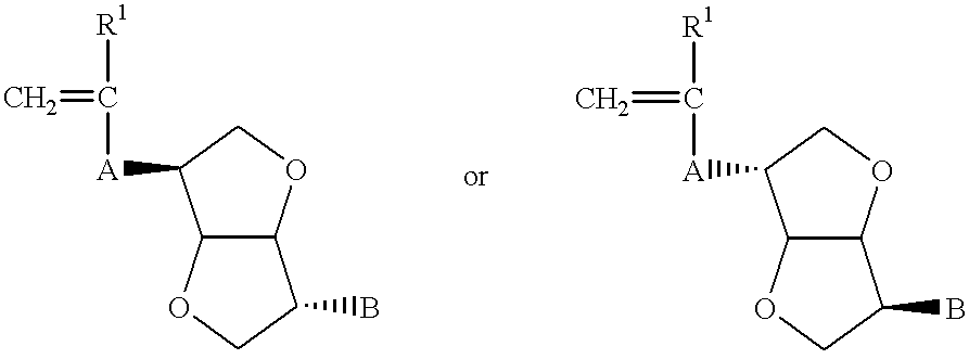
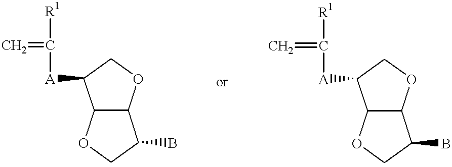
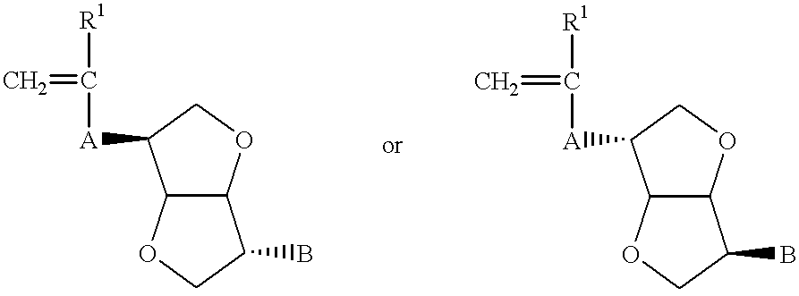
To obtain a monomer having a large torsion force, to obtain a liquid crystal polymer which is excellent in a film-forming property, can easily control a helical pitch of a cholesteric phase, can form a grandjean orientation in a good monodomain state by an orientation treatment in a short time such as few minutes, and can stably fix it in a glass state, and to obtain an optical element having a circular dichroism, represented by the following formula (a), comprising a solidified product of the liquid crystal polymer, which is thin and light, is hard to change the oriented state such as pitch, etc., at a practical temperature, and has excellent durability and storage stability.An optically active monomer represented by(wherein R1 represents a hydrogen atom or a methyl group, and A and B represent an organic group); a side chain type liquid crystal polymer having a structural unit comprising the optically active monomer; and an optical element showing a circular dichroism having a solidified layer of a grandjean oriented cholesteric liquid crystal phase comprising the liquid crystal polymer.

Description

The present invention relates to an optically active monomer and a liquid crystal polymer thereof suitable for forming a liquid crystal display, and to an optical element having a circular dichroism using the polymer.A polarizing film prepared by adsorbing a dichromatic dye, etc., to a stretched film, such as a stretched polyvinyl alcohol film, etc., cannot be effectively used because at least 50% of an incident light is absorbed, and thus it is difficult to increase a luminance and decrease a consumed electric power of a liquid crystal display device, etc. As a result, an optical element having a circular dichroism has been expected. This is because a helical axis of a liquid crystal molecule causes a vertical grandjean orientation to the optical element, in the natural light striking in parallel to the helical axis (incident angle: 0 degree), about a half of the light of a certain wavelength is reflected as a right (or left) circularly polarized light, residual about a half of the...

Claims


Application Information

Patent Timeline
Patent Type & Authority Patents(United States)
IPC IPC(8): C08F20/00C08F20/30C08F20/26C07D493/00C07D493/04C09K19/34C09K19/38G02B5/30
CPCC07D493/04C08F20/26C08F20/30C09K19/3861G02B5/3016C09K2019/3408
Inventor IZUMI, KYOKONAKANO, SHUSAKUMOCHIZUKI, AMANE
Owner NITTO DENKO CORP
Why Eureka
Eureka Blog
Learn More