
Safety valve element for capacitor and capacitor case lid with safety valves

a safety valve and capacitor technology, applied in the direction of functional valve types, cell components, cell component details, etc., can solve the problems of not uniformly hardened, spoiled sealability of the vessel, and not always ruptured

Inactive Publication Date: 2001-07-10
TOYO KOHAN CO LTD
View PDF12 Cites 19 Cited by
  • Summary
  • Abstract
  • Description
  • Claims
  • Application Information

AI Technical Summary

Benefits of technology

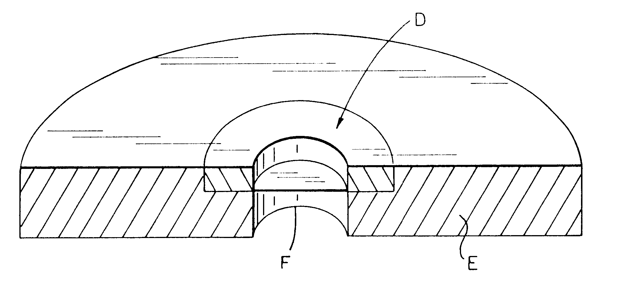
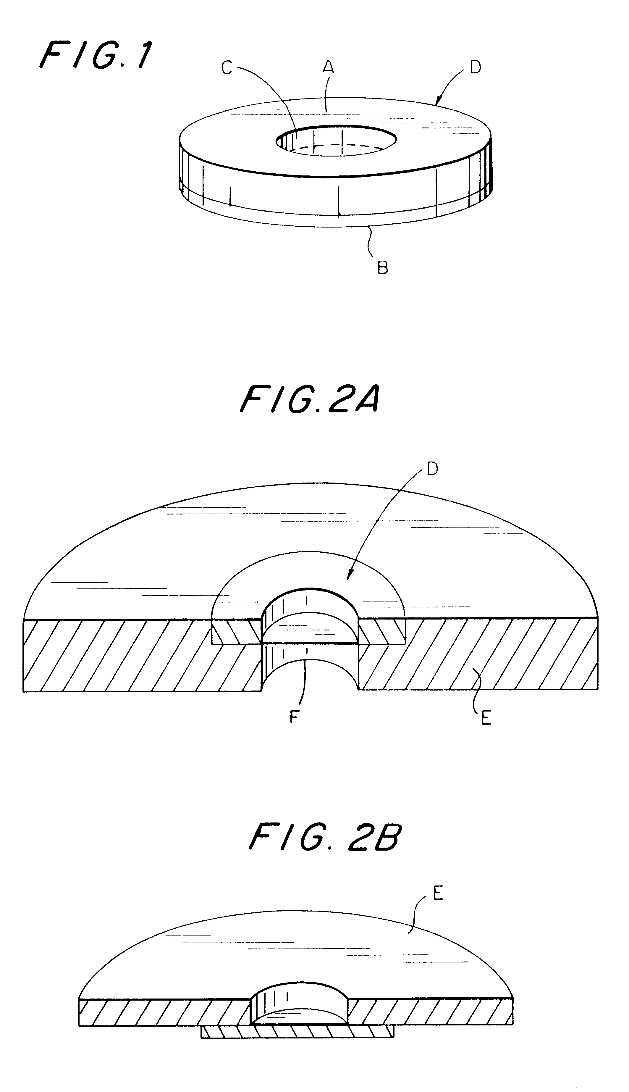
The safety valve elements for a condenser use according to the present invention can readily provide a portion to be ruptured having a uniform thickness so that the safety valve can rupture at inner pressures of the condenser in a stable pressure range. Accordingly, when such a safety valve element for a condenser use is used as a safety valve of various kinds of pressure vessels or the like, they can be reliably operated with its stable operating pressure.The safety valve element for a condenser use according to the present invention is made of a composite material which is produced using a cold pressure welding so that the lowering of the strength of material can be minimized compared to that by the conventional high temperature heat welding method thus realizing its stable operating pressure.Furthermore, the condenser case lid according to the present invention is formed after forming a perforated opening in the metal substrate and pressure welding the metal foil, which is to work as a safety valve, to the metal substrate so that the condenser case lid provided with a rupture portion working as a safety valve can be directly and readily produced. Accordingly, when they are used as a condenser case lid with a safety valve, they can be reliably operated with its stable operating pressure.Furthermore, the condenser which incorporates the safety valve elements for a condenser use according to the present invention can be operated with a stable operating pressure thus assuring an optimum safety.

Problems solved by technology

And, during press working to obtain an extremely thin wall part, fine or minute cracks may occur in the thinned wall part, and once such cracks occur, sealability of the vessel is spoiled.
Although the thinned wall part is hardened by such press working, it is not uniformly hardened.
Accordingly, the release valve as mentioned above has another drawback that even if the thinned wall part is pressed to have a uniform thickness, it does not always rupture at a constant pressure.
Furthermore, an etching method has been proposed to make thinner a part of the wall of the condenser vessel, however, it is extremely difficult to control the thickness of the thinned wall part at a prescribed thickness after etching.
Thus, when using the above mentioned method, it is extremely difficult to obtain a thinned wall part having a uniform thickness.
This method, however, cannot provide such high sealability as required for the condenser which uses organic solvent as the electrolyte.
Resultantly, when the inner pressure of the condenser is excessively elevated, the condenser vessel itself ruptures, and so broken pieces of the condenser vessel scatter, or the contents blow off, which may possibly impair the safety.
Besides, such a thick metal foil is not economically favorable.
When the frequency is less than 1 MHz, it is difficult for the high frequency power source to hold a stable glow discharge, which prevents a continuous etching.
On the other hand, when the frequency is more than 50 MHz, the high frequency power source is liable to oscillate and a power supply system becomes unfavorably complicated.
When the pressure of argon gas is not more than 1.times.10.sup.-4 Torr., it is difficult to stably keep the glow discharge and a high ion flow cannot be obtained, which prevents a high speed etching.
A conventional cold rolling welding method cannot provide a strong welding even if the surfaces of the metals are sufficiently activated.
It is not desirable that the rolling reduction rate exceeds 30%, since such a high rolling reduction rate induces remarkably high work hardening.

Method used


Image

  • Safety valve element for capacitor and capacitor case lid with safety valves
  • Safety valve element for capacitor and capacitor case lid with safety valves
  • Safety valve element for capacitor and capacitor case lid with safety valves

Examples


example 2

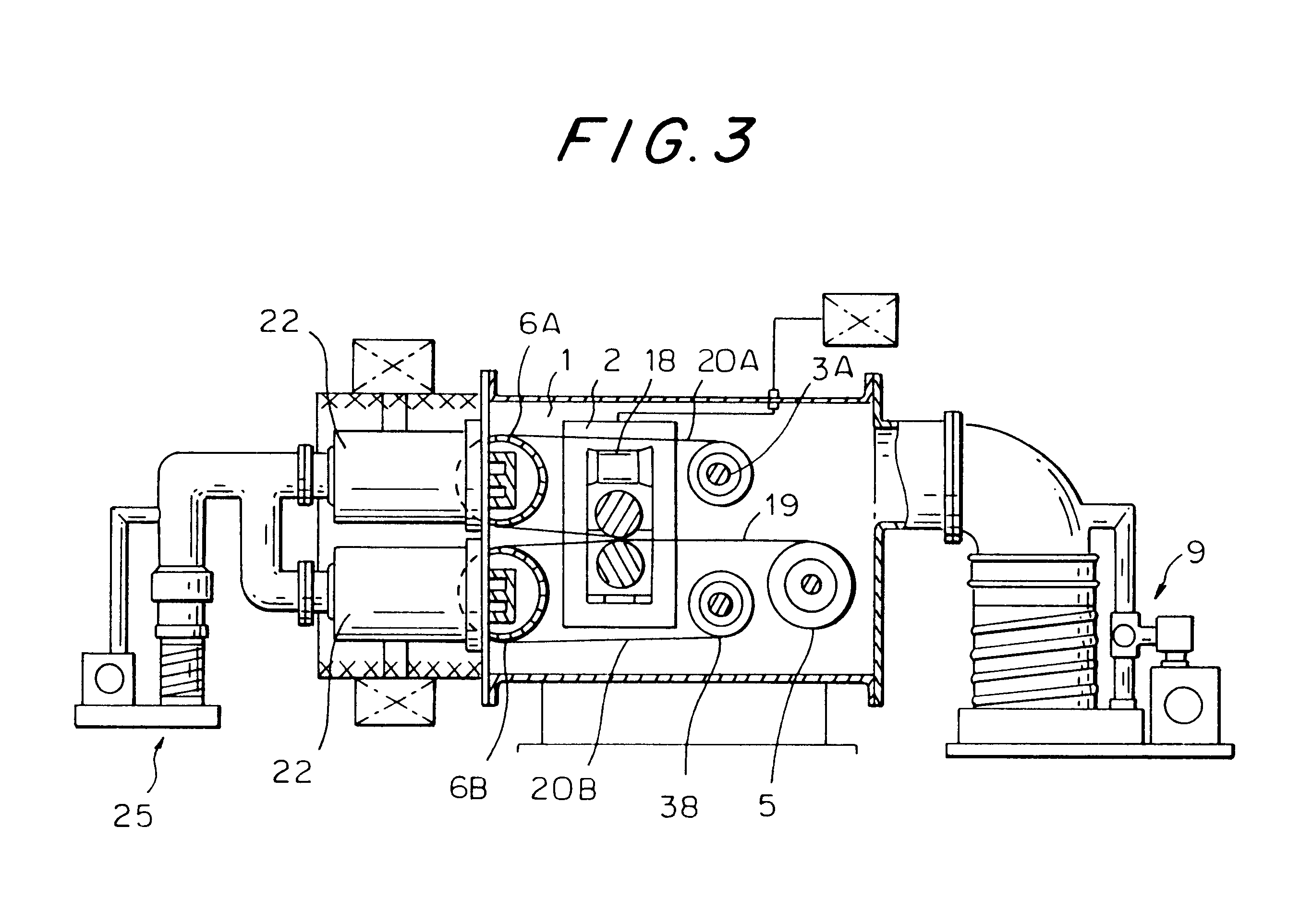
An aluminum sheet of JIS A3004 type having a thickness of 0.4 mm was perforated using a punch press to form circular openings each having a diameter of 2 to 7 mm to prepare an aluminum substrate. The aluminum substrate and an aluminum foil (AIN 30, Al085) having a thickness of 30 .mu.m were inserted into a vacuum chamber of argon gas atmosphere having a vacuum level of 1.times.10.sup.-2 Torr. so as to provide an etching of approximately 500 angstrom on one surface of the cold-rolled and perforated aluminum substrate and the same etching on one surface of the aluminum foil, which surface was to oppose to the etched surface of the metal substrate, by the magnetron sputtering method. Subsequently, the aluminum substrate and the aluminum foil were laminated such that the etched surfaces of them were made to contact each other and pressure welded by cold rolling at a room temperature and with a rolling reduction rate of 2% to produce a composite material.

A plurality of safety valve eleme...


PUM


Abstract

The object of the present invention is to provide safety valve elements for condenser use, which rupture precisely at a predetermined pressure especially stably in a low pressure range so as to release inner pressure outside and can be manufactured readily, and to provide a condenser which incorporates the safety valve elements.The safety valve elements for condenser use according to the present invention comprises a metal substrate A which is provided with a perforated opening C and a metal foil B laid over the metal substrate A to close the perforated opening C.

Description

The present invention relates to especially safety valve elements for condenser use which can be broken off at the low prescribed presser and release the internal presser, condenser case lids provided with safety valves and condensers produced by employing such safety valve elements and condenser case lids.PRIOR ARTSConventionally, a condenser which uses an organic solvent as an electrolyte sometimes suffers rupture when the pressure in the condenser is abnormally elevated. To prevent the occurrence of such rupture when the pressure in the condenser is excessively increased, various safety valves with different mechanisms have been proposed in the request of safety valves capable of releasing inner pressure outside. The safety valves need to be operated particularly at a low pressure of not more than 2 to 5 kgf / cm.sup.2 so as to assure the safety for fear that broken pieces or contents of the condenser would scatter outside to thereby hurt human body, if the condenser ruptures by a ...

Claims


Application Information

Patent Timeline
IPC IPC(8): H01G9/08H01G9/12H01G9/04
CPCH01G9/12Y10T137/1714H01G9/04
Inventor SAIJO, KINJIYOSHIDA, KAZUOYOSHIMOTO, NOBUYUKIISOBE, YOSHIHIKO
Owner TOYO KOHAN CO LTD
Learn More