Exhaust emission control system of hybrid car

a technology of exhaust emission control and hybrid cars, which is applied in the direction of machines/engines, combustion-air/fuel-air treatment, transportation and packaging, etc., can solve the problems of not being able to effectively activate the catalyst, the catalyst cannot function effectively, and the load on the engine fuel injection device increases

Inactive Publication Date: 2001-07-31
TOYOTA JIDOSHA KK
View PDF21 Cites 56 Cited by
  • Summary
  • Abstract
  • Description
  • Claims
  • Application Information

AI Technical Summary

Problems solved by technology

Accordingly, a load on the engine fuel injection device increases, which might cause a fault in the engine fuel injection device.
In this case, therefore, it may be possible that the catalyst cannot function effectively as exhaust gas purifying means for a while until it is activated.
Further, if the hybrid car adopts the internal combustion engine, such as a direct injection engine and a diesel engine, exhibiting a high thermal efficiency and producing small quantities of hydrocarbon and carbon monoxide with an excessive oxygen in an atmosphere in an exhaust system, and when, for instance, the internal combustion engine is in an operation state such as a light load region, an exhaust gas temperature at that time is low with the result that heat enough to activate the catalyst is not trans

Method used


Image

  • Exhaust emission control system of hybrid car
  • Exhaust emission control system of hybrid car
  • Exhaust emission control system of hybrid car

Examples


first embodiment

the present invention will be discussed referring to FIGS. 1-3.

(Outline of System Architecture of Hybrid Car)

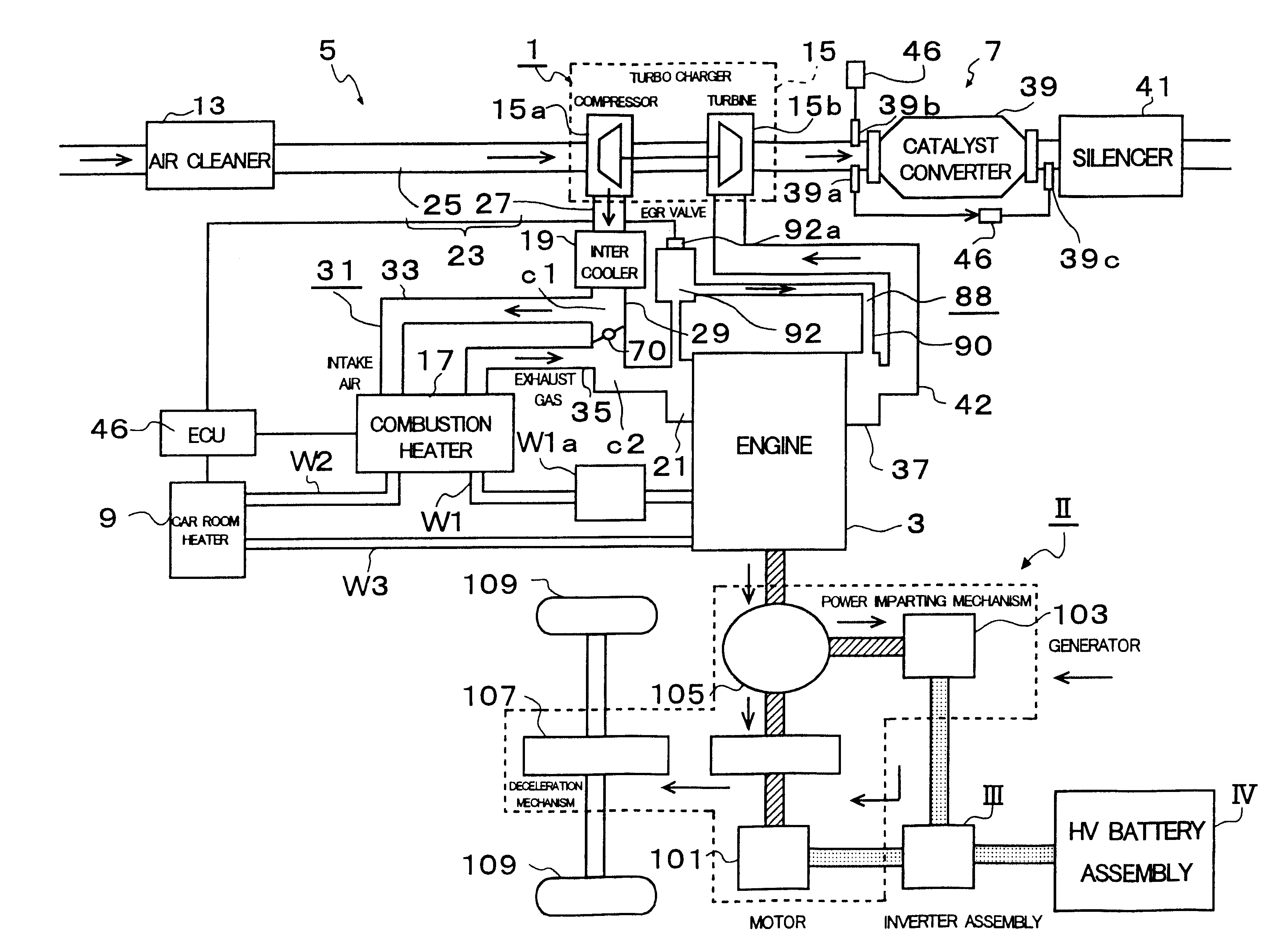
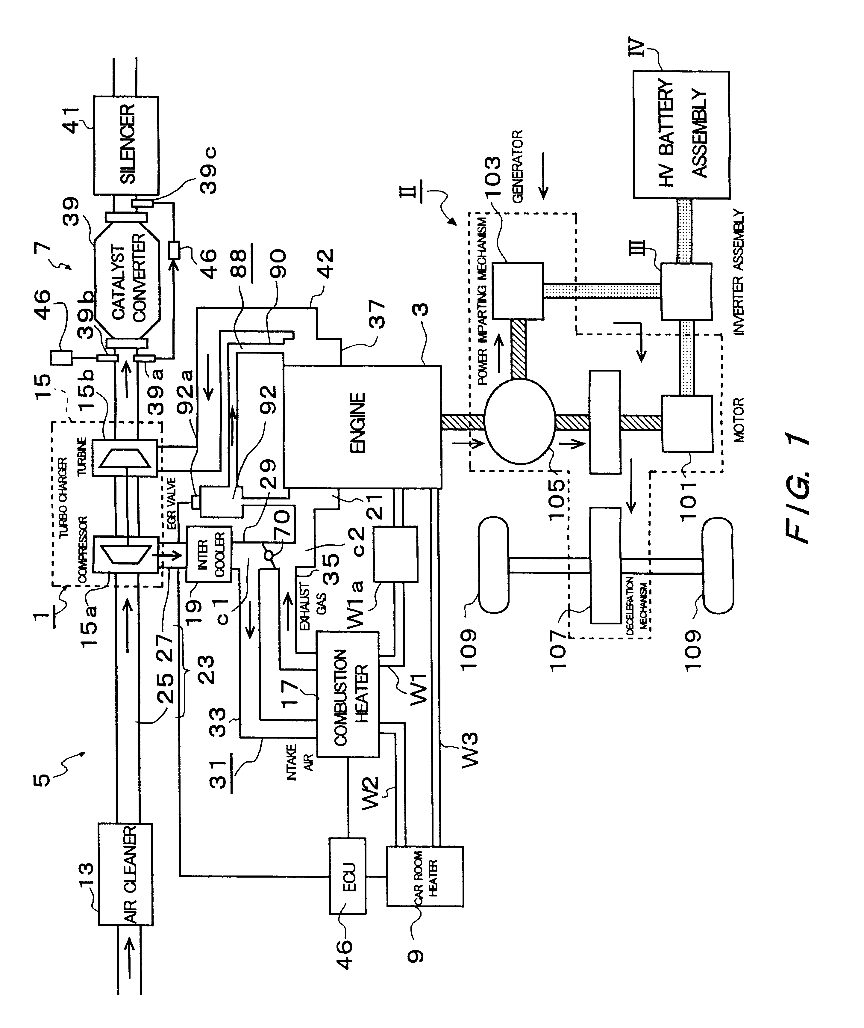
What is shown in FIG. 1 is a system architecture of a hybrid car which travels by two types of power sources of an engine and a motor. This system architecture includes a diesel engine I functioning as a main power source of the hybrid car, a hybrid-oriented Trans-axle II including an electric motor 101 functioning likewise as a sub-power source, an inverter III for controlling the electric power to the electric motor 101, and a battery IV for supplying and collecting the electric power by a predetermined voltage. Note that neither the inverter III nor the battery IV is related directly to the present invention, of which detailed explanations are therefore omitted, and the diesel engine I and the hybrid-oriented Trans-axle II will hereinafter be discussed in details.

(Diesel Engine I)

A diesel engine 1 serving as an internal combustion engine has an engine body 3 equipped with ...

second embodiment

The exhaust emission control system of the hybrid car in a second embodiment will be described with reference to FIGS. 5-7.

The followings are differences of the second embodiment from the first embodiment. A difference (1) is that the heater branch pipe 31 is connected to the upstream-side connecting pipe 25, instead of being connected to the mainstream pipe 29 of the downstream-side connecting pipe 27 in the first embodiment. A difference (2) is a branch pipe 95 provided midways of the combustion gas discharge passageway 35 and extending downstream of the intake throttle valve 70. A difference (3) is a three-way valve 97 provided, as a valve device which opens only when the combustion heater is operated, at a diverging point of the combustion gas discharge passageway 35 to the branch pipe 95. Therefore, the same components are marked with the like numerals, and their explanations are omitted.

As shown in FIG. 5, the heater branch pipe 31 is connected to the upstream-side connecting ...

third embodiment

The exhaust emission control system of the hybrid car in a third embodiment will be described with reference to FIGS. 8-10.

The followings are differences of the third embodiment from the second embodiment. A difference (1) is a provision of a combustion gas passageway 99 diverging from the branch pipe 95 and extending anterior to the catalyst 39 of the exhaust pipe 42. A difference (2) is that a three-way valve 97' is added at a branch pipe 95 connecting point between the combustion gas passageway 99 and the branch pipe 95, and there are provided two pieces of three-way valves designated respectively by 97 and 97'. Hence, the same components are marked with the like numerals with an omission of their explanations.

(Combustion Gas Passageway 99)

The combustion gas passageway 99 serves to send the combustion gas, which comes from the combustion heater 17 and arrives at the branch pipe 95 via the three-way valve 97, towards anterior to the catalyst 39 without letting this combustion gas ...


PUM


Abstract

An exhaust emission control system of a hybrid car capable of relieving a load upon an engine fuel injection device by eliminating a use of sub-injection and recovering from S-poisoning as well as purifying an exhaust gas even by eliminating the use of sub-injection. The exhaust emission control system of an internal combustion engine, used for the hybrid car traveled by two types of power sources of a diesel engine and an electric motor, includes a combustion heater as separate body from the engine, a catalyst, provided in an exhaust passageway, for purifying an engine exhaust gas, a combustion gas passageway through which a combustion gas emitted from the combustion heater flows toward the catalyst, and a three-way valve for introducing the combustion gas to the catalyst via the combustion gas passageway or an EGR passageway when the diesel engine is in a stop state and when the electric motor is in a driving state.

Description

1. Field of the InventionThe present invention relates generally to an exhaust emission control system of a hybrid car, and more particularly to an exhaust emission control system relative to an internal combustion engine of the hybrid car provided with two types of power sources such as an internal combustion engine and an electric motor and traveled by optimally combining driving forces generated by these two types of power sources corresponding to a condition.2. Related Background ArtA hybrid car also adopts an internal combustion engine, such as a gasoline direct-injection lean burn engine and a diesel engine etc, exhibiting a high thermal efficiency and producing small quantities of hydrocarbon and carbon monoxide with an excessive oxygen in an atmosphere in an exhaust system.For example, an occlusion reduction type lean NOx catalyst may be one of catalysts used in the exhaust system as an element for purifying an exhaust gas of the internal combustion engine described above. T...

Claims


Application Information

Patent Timeline
IPC IPC(8): B60K6/00B60K6/04F01N3/08F01N3/20F02M25/07B60K6/20B60K6/24B60K6/445B60W10/06B60W10/26B60W10/30B60W20/00F01N3/24F02M31/06
CPCB60K6/24B60W10/06B60W10/26F01N3/0871F01N3/0885F01N3/2033F02M25/0707F02M25/0742F02M31/08B60K6/445Y02T10/6239F02B29/0406Y02T10/121Y02T10/6295Y02T10/126Y02T10/26Y10S903/903Y10S903/905F02M26/05F02M26/36Y02T10/12Y02T10/62Y02A50/20
Inventor SUZUKI, MAKOTOKOBAYASHI, HIDEOHAYASHI, KOTARO
Owner TOYOTA JIDOSHA KK
Why Eureka
Try Eureka