Cutting tool and method of making same

a cutting tool and cutting method technology, applied in the field of cutting tools, can solve the problems of high temperature at the tool/workpiece interface, high cost, enhanced wear, etc., and achieve the effects of improving oxidation resistance, improving adhesion, and improving wear resistan

Inactive Publication Date: 2001-09-04
WIDIA
View PDF16 Cites 39 Cited by
  • Summary
  • Abstract
  • Description
  • Claims
  • Application Information

AI Technical Summary

Benefits of technology

It is the principal object of the present invention to provide a tool of the aforedescribed type which has an improved wear resistance

Problems solved by technology

At high cutting speeds and/or large cutting cross sections, the high temperatures at the tool/workpiece interface give rise to enhanced wear, especially with workpieces which are difficult to machine, and ultimately to breakage of the tool.
To minimize the temperatures which develop in machining of such workpieces, i.e. at the chip-forming region, coolants and lubricants can be used which are environmentally unsound and can p

Method used


Image

  • Cutting tool and method of making same
  • Cutting tool and method of making same

Examples


examples

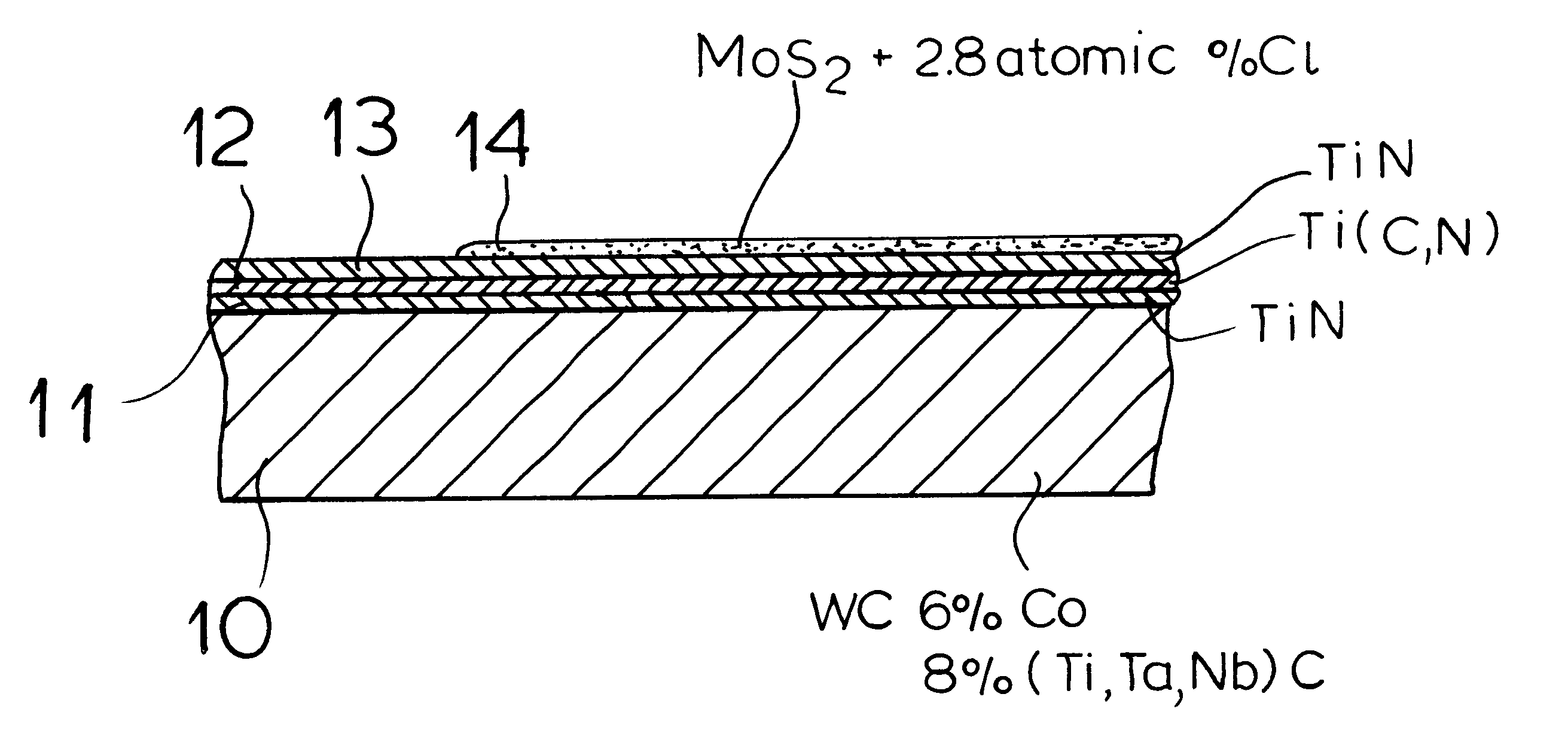
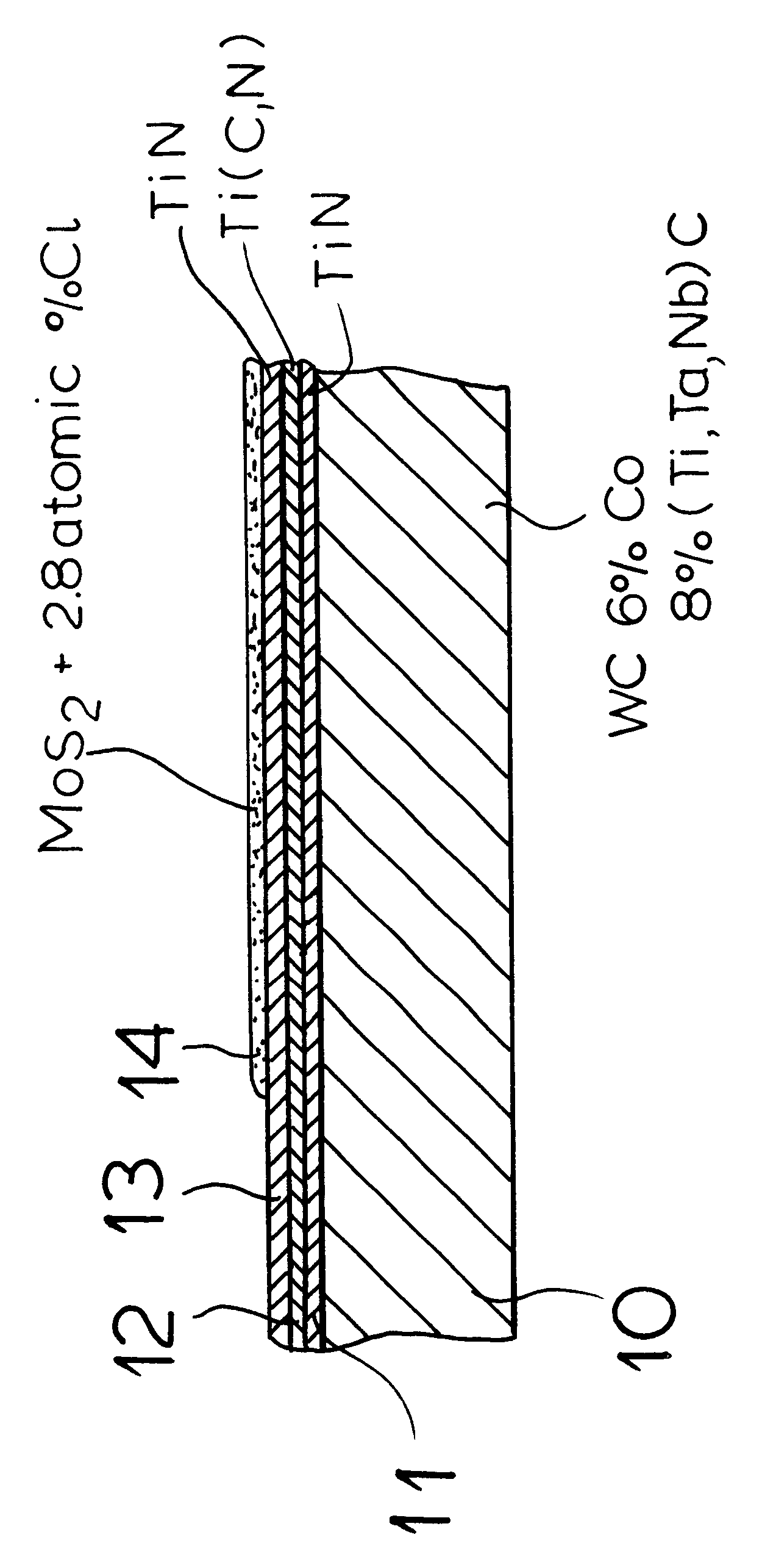
In a series of tests different substrate materials were coated in a heated quartz glass tube. These included uncoated cutting inserts as well as inserts previously coated with titanium nitride / titanium carbonitride / titanium nitride layer sequences as well as thin silicon disks for analytical study. The reactive gas mixture was generated by supplying argon over molybdenum pentachloride in a separate flask and then mixing the product with argon and hydrogen sulfide. The temperature in the quartz gas tube was available between 300.degree. C. and 800.degree. C. The pressure could be controlled between 0.1 and 50 kPa. For control of the flow rate, a flow meter was used. Respective atomic compositions of the produced single or outer layer was determined by wavelength dispersive X-ray spectroscopy. By X-ray diffraction studies of the deposited layers, the proportions in the solid phases of silicon Mo.sub.2 S.sub.3 were determined. Especially high proportions (greater than 70 volume %) of h...


PUM

PropertyMeasurementUnit
Percent by atomaaaaaaaaaa
Percent by volumeaaaaaaaaaa

Abstract

A tool having a substrate and at least as a sole layer or the outermost layer, a coating of the molybdenum sulfide containing 0.5 to 6 atomic % chlorine.

Description

The present invention relates to a cutting tool of the type in which a substrate, usually of a hard metal, cermet, ceramic or steel, is coated with at least one layer and in which the outermost layer of the coating is a molybdenum sulfide layer. The invention also relates to a method of making such a tool with an outermost molybdenum sulfide layer.The coating of substrate bodies of hard metal, cermets, ceramics or steel with hard-facing and wear-reducing layers of hard materials, mixtures of hard materials or ceramics, is known in the production of cutting tools. The coatings can be carbides, nitrides, carbonitrides, oxycarbonitrides, oxides and / or borides of an element from Groups IVa to Via of the Periodic Table. Examples of such wear-reducing materials include TiC, TiN, Ti(C,N) and ceramics like Al.sub.2 O.sub.3 and ZrO.sub.2. At high cutting speeds and / or large cutting cross sections, the high temperatures at the tool / workpiece interface give rise to enhanced wear, especially wi...

Claims


Application Information

Patent Timeline
IPC IPC(8): C23C16/30C23C28/00C23C30/00
CPCC23C16/305C23C28/00C23C30/00C23C30/005C23C28/044Y10T428/265
Inventor KONIG, UDOENDLER, INGOLFLEONHARD, ALBRECHT
Owner WIDIA
Why Eureka
Try Eureka