
Acoustic time of flight and acoustic resonance methods for detecting endpoint in plasma processes

a plasma process and acoustic resonance technology, applied in the field of acoustic time of flight and acoustic resonance methods for detecting endpoints in plasma processes, can solve problems such as endpoint detection variability, and achieve the effect of reducing the molecular density of gas molecules in gas and increasing the mean free path

Inactive Publication Date: 2002-04-09
BELL SEMICON LLC +1
View PDF7 Cites 17 Cited by
  • Summary
  • Abstract
  • Description
  • Claims
  • Application Information

AI Technical Summary

Benefits of technology

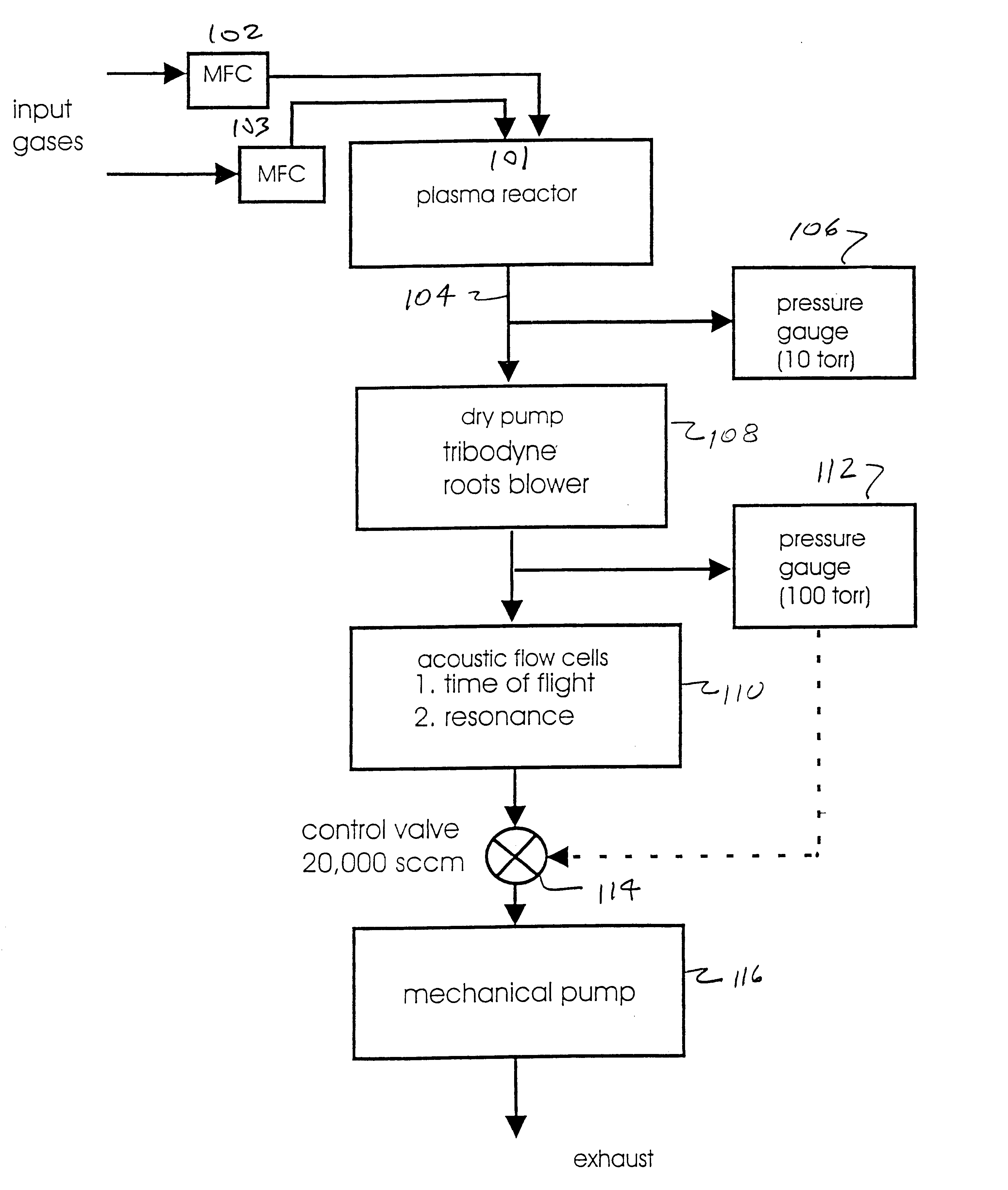
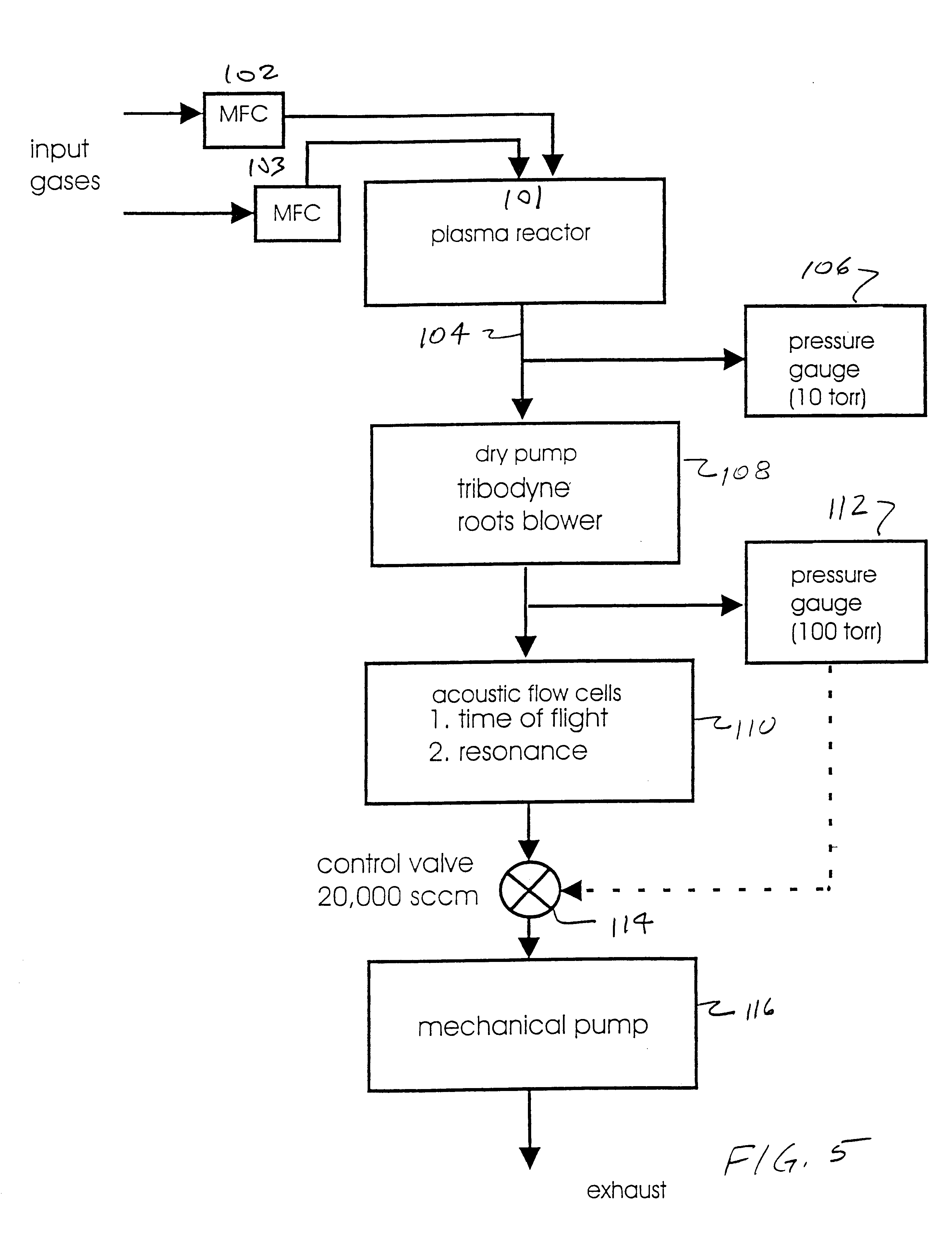
The present invention overcomes the above described detriment, in a preferred embodiment, by exhausting all of the gas stream through the acoustic cell, rather than just a portion, and using an exhaust control valve to regulate the pressure in the acoustic cell to a preselected, high value such as up to about 100 torr. A first pump, such as a vacuum pump, is used to pressurize the gas stream entering the acoustic cell from the plasma chamber. A controllable valve is fitted to an exhaust port of the acoustic cell and serves to regulate the outflow of the gas stream from the acoustic cell. A pressure monitor is coupled to the acoustic cell and to the controllable valve. The pressure monitor provides signals to the valve to adjust the gas stream outflow in a manner to maintain a substantially constant pressure in the cell. Constant pressure regulation in the acoustic cell is believed to produce more precise endpoint detection than the unregulated pressure method.
It will be apparent from a comparison of FIGS. 5 and 6 that the present invention provides an active control system which regulates the gas stream pressure in the acoustic cell while the prior system provided only an unregulated gas stream. Accordingly, the pressure in the acoustic cell 200 of the prior system, while greater than about 10 torr, could vary between that value and substantially higher. In the present invention, it is preferable to direct the entire gas stream through the acoustic cell 110. Further, the present invention reduces the number of pumps required to process the exhaust gas stream.

Problems solved by technology

Applicants have found that variation in pressure can affect acoustic cell response and thereby cause variation in endpoint detection.

Method used


Image

  • Acoustic time of flight and acoustic resonance methods for detecting endpoint in plasma processes
  • Acoustic time of flight and acoustic resonance methods for detecting endpoint in plasma processes
  • Acoustic time of flight and acoustic resonance methods for detecting endpoint in plasma processes

Examples


example 2

The acoustic cell described in Example 1 was filled with air that had a temperature of about 25.degree. C. The air in the acoustic cell was kept at a pressure of about 20 torr. Acoustic signals were transmitted a distance of about 3 inches from the transmitter to the detector, according to the same conditions described in Example 1.

A DSA Model 602 digitizing signal analyzer was used to monitor the acoustic signals transmitted through the air in the acoustic cell. A trace from the digitizing signal analyzer is illustrated in FIG. 12. The pulse, denoted as 910, is the transmitted acoustic signal. The pulse, denoted as 915, is the detected acoustic signal. FIG. 12 illustrates the capability of transmitting acoustic signals through air at pressures of about 20 torr.

example 3

The acoustic cell described in Example 1 was filled with tetraethyl orthosilicate (TEOS) gas in oxygen that had a temperature of about 32.degree. C. The TEOS gas in the acoustic cell was kept at a pressure of about 14 torr.

Acoustic signals which had a frequency of about 200 kilohertz were transmitted through the TEOS gas in the acoustic cell from the transmitter to the detector with a repetition rate of about 100 hz. The acoustic signals traveled a distance of about 3 inches from the transmitter and the detector.

A DSA Model 602 digitizing signal analyzer was used to monitor the acoustic signals transmitted through the TEOS gas in the acoustic cell. A trace from the digitizing signal analyzer is illustrated in FIG. 11. The pulse, denoted as 940, is the transmitted acoustic signal. The pulse, denoted as 945, is the detected acoustic signal. Additional pulses shown on the trace which surround those denoted as 940 and 945 are attributed to noise from the acoustic cell. FIG. 11 illustrat...


PUM


Abstract

A method for determining the endpoint of a plasma etch process is disclosed. The endpoint of the plasma etch process is determined using an acoustic cell attached to an exhaust port on a reaction chamber of a plasma reactor. The gas from the reaction chamber flows into the acoustic cell during the plasma etch process. Acoustic signals are periodically transmitted through the gas flowing in the acoustic cell and a first velocity for the acoustic signals associated with etching a first material layer formed on a substrate is determined. Thereafter, the endpoint of the plasma etch step is determined when the first velocity changes to a second velocity associated with etching the first material layer through its thickness to its interface with an underlying material layer. The gas from the reaction chamber flows through a compressor prior to flowing into the acoustic cell to increase the gas pressure in the acoustic cell.

Description

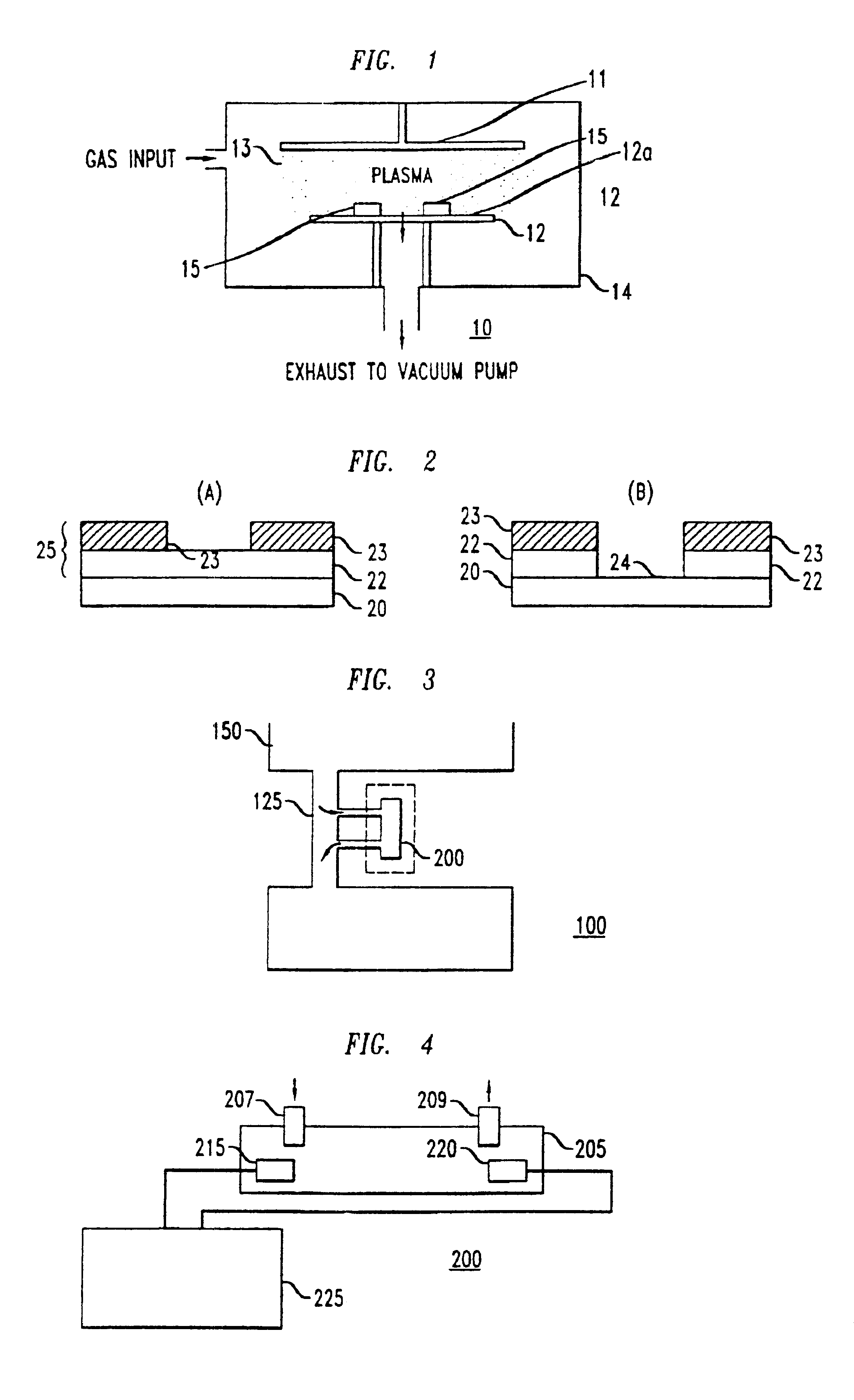
The present invention relates generally to plasma systems and, more particularly, to a method for determining the endpoint of a plasma etch process.In many processes for microelectronic device fabrication, a pattern defined by a lithographic technique is transferred through a layer of material formed on the surface of a substrate. Typically, the pattern is transferred by etching using a plasma. The term plasma, as used in this disclosure, refers to a partially ionized gas consisting of positively and negatively charged molecular species, as well as neutrals.Plasma etching processes are typically performed in an apparatus such as a plasma reactor. Plasma reactors generally include a reaction chamber, a plasma generating system, a wafer holder and handling system and a gas delivery system (i.e., inlet, exhaust, and flow control). The term reaction chamber, as used in this disclosure, refers to the area within a plasma reactor where ionized gases physically and / or chemically interact w...

Claims


Application Information

Patent Timeline
IPC IPC(8): G01N29/02G01N29/32G01N29/024G01N29/22H01J37/32
CPCG01N29/024G01N29/223G01N29/323G01N29/326H01J37/32963H01J37/32935G01N2291/02836G01N2291/02872G01N2291/011
Inventor REITMAN, EDWARD ALOISCADET, GARDY
Owner BELL SEMICON LLC
Learn More