Optical pulse stretching and smoothing for ArF and F2 lithography excimer lasers

a technology of excimer lasers and optical pulses, which is applied in the direction of laser details, optical resonator shape and construction, electrical apparatus, etc., can solve the problems of large optical lenses used, the laser pulse duration has an upper limit of a few tens of nanoseconds, and the problem of large optical lens use, etc. problem, to achieve the effect of smoothing the temporal pulse envelope, and reducing the cost of laser equipmen

Inactive Publication Date: 2002-05-14
COHERENT GMBH
View PDF25 Cites 88 Cited by
  • Summary
  • Abstract
  • Description
  • Claims
  • Application Information

AI Technical Summary

Benefits of technology

The object of the invention is to stretch the laser pulse of ArF- and F.sub.2 -excimer lasers using various improved designs of optical delay lines, including, if necessary, imaging optics. To provide stable optics, the delay line comprises a minimum of optical components with high reflecting coatings and uses as much as possible total internal reflection for beam direction changes. Furthermore, by using delay lines with multiple points of output coupling and multiple, parallel beam pathways, it is possible to achieve an even smoother shape and greater stretching of the temporal pulse profile. By this method it is possible to greatly smooth the temporal pulse envelope in order to avoid peaks with high intensity.
By this invention the already known principle of optical pulse stretching by employing optical delay lines is further developed for deep UV (DUV) ArF- and F.sub.2 -excimer lasers with a pulse length of a few tens of nanoseconds. The invention contains methods to achieve very high pulse energy transmission even in the deep UV. Using this technique, stretching factors >2 can be easily achieved.

Problems solved by technology

For photolithography imaging very expensive and large optical lenses are used.
The shorter the wavelength, the greater is the problem of photoinduced damage of the employed optical components.
Due to the highly complex electrical discharge process needed for the generation of light emitting excimer states, the laser pulse duration has an upper limit of a few tens of nanoseconds.
The disadvantages of pulse stretching methods using electrical rather than optical methods are that other important laser beam parameters such as pulse-to-pulse stability or pointing stability are strongly influenced as well.
However, this time it is the reflected light portion which exits the optical delay device.
One limitation of this prior art device was therefore the effect of refraction on the optical spread of the laser beam.
However, while this approach eliminates the problems due to refraction and the need to keep reflective surfaces tightly aligned, an important limitation was the substantial transmission losses of light energy by passage through the optical fiber.
Such losses especially limit the applicabiity of this design to UV and DUV laser light.
One limitation of this compensation plate arrangement was that light beams which underwent multiple refractions upon passage through multiple loops of the optical delay circuit, were corrected for only a single refraction event, and not the additional refractions involved in their multiple or iterative passages through the circuit.
The design of the above optical delay lines limits their ability to stretch out a laser pulse and smooth the temporal profile of the optical pulse.

Method used


Image

  • Optical pulse stretching and smoothing for ArF and F2 lithography excimer lasers
  • Optical pulse stretching and smoothing for ArF and F2 lithography excimer lasers
  • Optical pulse stretching and smoothing for ArF and F2 lithography excimer lasers

Examples


Embodiment Construction

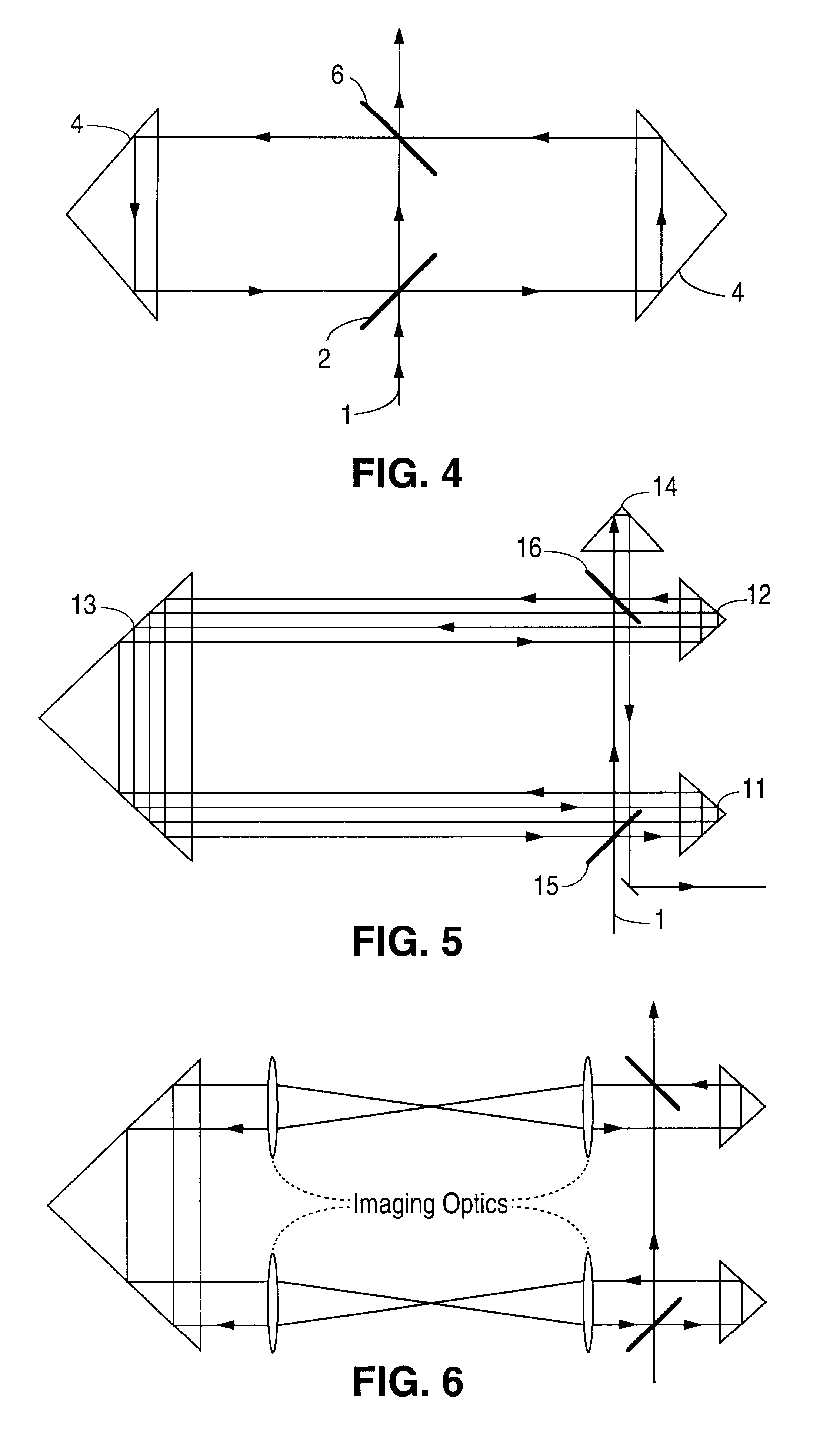
The object of this invention is to stretch the emitted laser pulse of ArF-and F.sub.2 -excimer lasers by using various types of optical delay lines and, if necessary, imaging optics. Furthermore, using delay lines it is possible to shape and to tune the temporal beam profile. In order to achieve this there are various possible setups of optical delay lines.

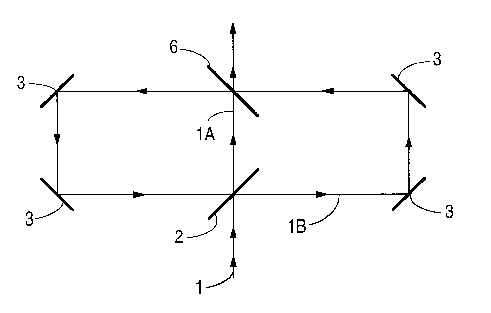
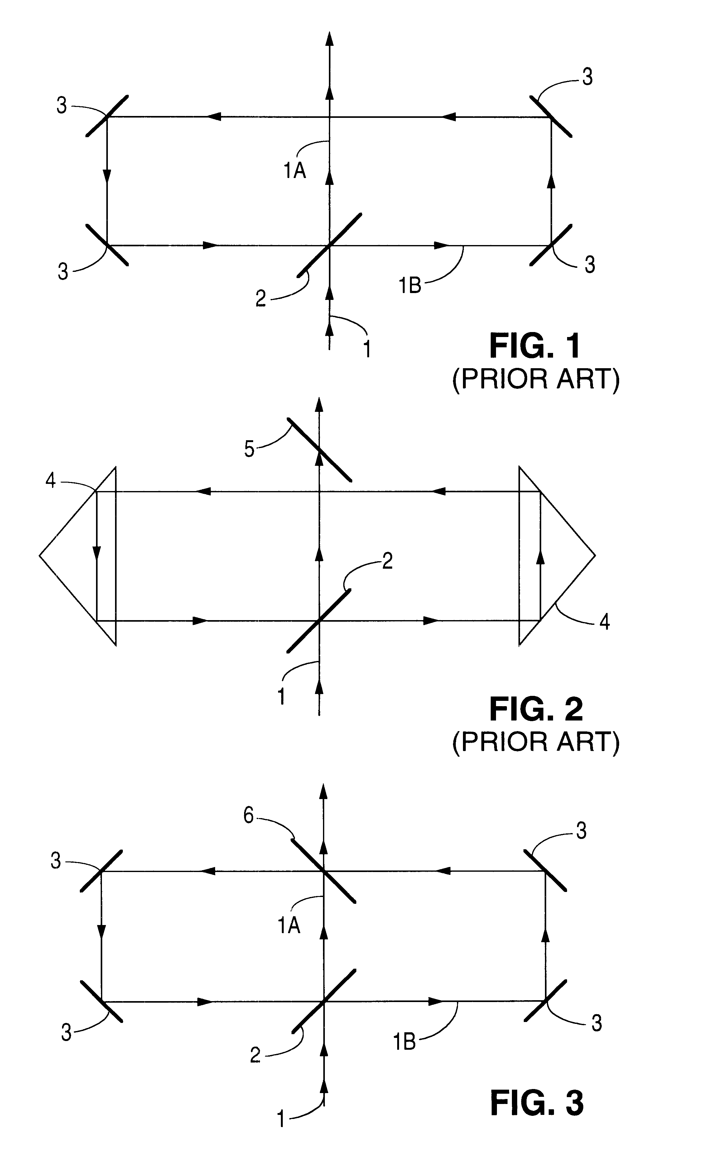
In the deep UV spectral range it is difficult to achieve high transmission for the radiation that passes through a delay line due to high absorption and scatter losses on dielectrically coated mirrors. Therefore, it is necessary to use a method that employs a minimum of high reflection coatings. Especially for industrial applications a delay line setup with a minimum of adjustment sensitivity has to be chosen. Several possible configurations are depicted in FIGS. 3-6.

In FIGS. 3 and 4, a second partially reflective mirror (6) is provided which provides a second point for diversion of a portion of the laser beam into the delay circu...


PUM


Abstract

A method and apparatus are provided for temporally stretching and smoothing of the pulses of an output beam of excimer and lithography lasers. The method and apparatus are based upon providing an optical delay line or circuit having a plurality of optical reflectors and a plurality of beam recombiners or splitters so arranged as to divide the pulse into numerous portions which vary in their travel time through the circuit. As a result, the energy of the incident pulse is greatly stretched and smoothed.

Description

The present invention relates to a method and apparatus for stretching and smoothing the laser pulses of a ArF and F.sub.2 -excimer lasers by using optical delay lines. The optical delay lines allow the shaping and tuning of the temporal beam profile of the laser pulses. More particularly, the present invention provides optical delay lines which provide multiple parallel beam paths and a plurality of locations for output coupling.Deep UV excimer lasers with wavelengths below 200 nm and high pulse energies of several mJ are applied in the photolithography resist exposure process used in the production of integrated circuits. For photolithography imaging very expensive and large optical lenses are used. The shorter the wavelength, the greater is the problem of photoinduced damage of the employed optical components. Color center formation and compaction effects are examples of such damage. The occurrence of optical material damage depends nonlinearly on the peak intensity of the applie...

Claims


Application Information

Patent Timeline
Patent Type & Authority Patents(United States)
IPC IPC(8): H01S3/00
CPCH01S3/0057Y10S372/70
Inventor MANN, KLAUSSCHRODER, THOMASSCHAFER, BERNDLEINHOS, UWESTAMM, UWE
Owner COHERENT GMBH
Why Eureka
Try Eureka