Jet propulsion power unit with non-metal components

a technology of jet propulsion and components, applied in the direction of rocket engine plants, machines/engines, light and heating apparatus, etc., can solve the problems of reducing the strength of the engine at temperatures of about 800.degree. c, affecting affecting the operation of the engine. , to achieve the effect of improving the stability of the engine, reducing the weight of the engine, and excellent strength characteristics

Inactive Publication Date: 2002-05-21
EADS SPACE TRANSPORTATION +1
View PDF6 Cites 17 Cited by
  • Summary
  • Abstract
  • Description
  • Claims
  • Application Information

AI Technical Summary

Benefits of technology

According to a preferred embodiment of the invention the body forming the combustion chamber, the nozzle, the expansion chamber and the insulation surrounding the body, are made of the same C/SiC composite material to thus provide the monolithic structure, whereby the temperature stability of the engine is increased while simultaneously reducing the weight of the engine with its insulation compared to conventional engines of comparable size made of high alloy steel.
It was found that C/SiC has excellent strength characteristics up to very high temperatures which allow using this material under difficult operating conditions. Additionally, C/SiC offers a low density in combination with a high resistance to abrasion, a high resistance to oxidation, an excellent temperature stability even at temperature fluctuations, and a high thermal fatigue strength combined with an absolute gas and liquid impermeability. A great variety of geometric configurations are easily realized with C/SiC as used according to the invention because machining is easy compared to high alloy steels. The present rocket engine component has an excellent thermal strength and a high heat conductivity that is even adjustable by selecting the porosity of the C/SiC material. This characteristic of a high heat conductivity allows for correspondingly low cooling capacities. Certain engines according to the invention can completely do without cooling due to the high thermal strength and excellent heat conductivity.
A distinction is made between C/SiC reinforced by long, continuous length carbon fibers, and C/SiC reinforced by short-length carbon fibers or whiskers. The material with continuous length carbon fibers can be laminated, pressed, or rolled. The resulting components have a particularly high mechanical strength combined with a particularly low density. The oxidation resistance of C/SiC can be improved by providing a suitable surface sealing. Such a sealing is not required for components made of short-fiber reinforced C/SiC because the material is especially resistant against oxidation and corrosion. Furthermore, C/SiC offers an extremely good heat dissipation due to its good heat conduction. This excellent characteristic is combined with an especially high thermal shock resistance. Moreover, C/SiC is particularly suitable for mechanical machining of blanks in a green state, whereby the combustion chamber cross-section, the nozzle cross-section and the expansion chamber cross-section can be machined to any

Problems solved by technology

Additionally, substantial pressure surges occur well above the normal operating conditions during certain operating ranges such as at ignition and when the engine is turned off.
These high alloy steels, for example Inconel.RTM., however still have th

Method used


Image

  • Jet propulsion power unit with non-metal components
  • Jet propulsion power unit with non-metal components
  • Jet propulsion power unit with non-metal components

Examples


first embodiment

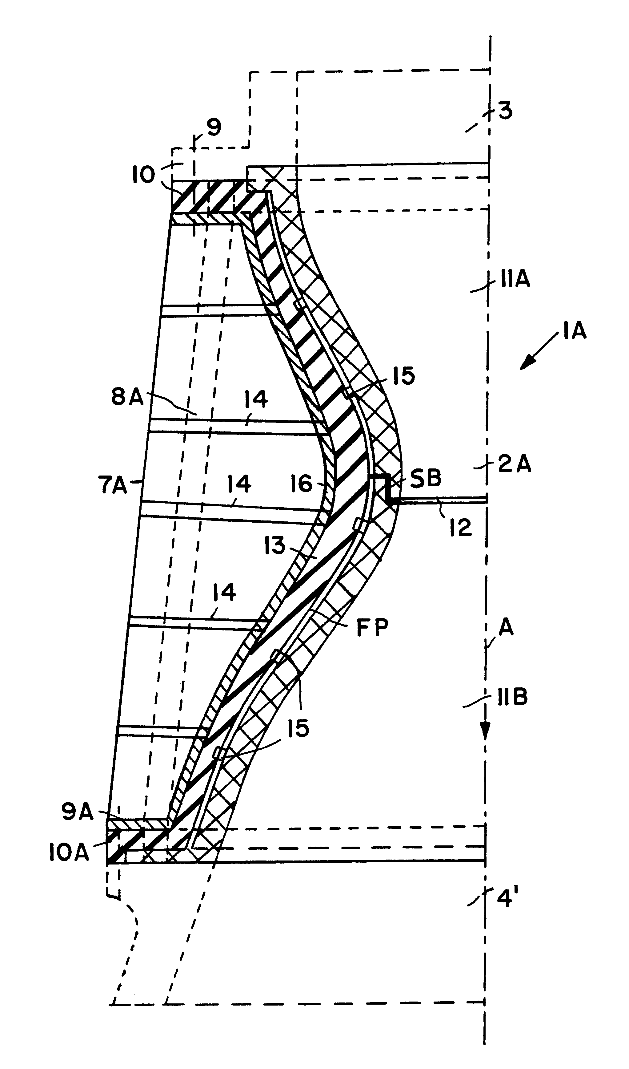
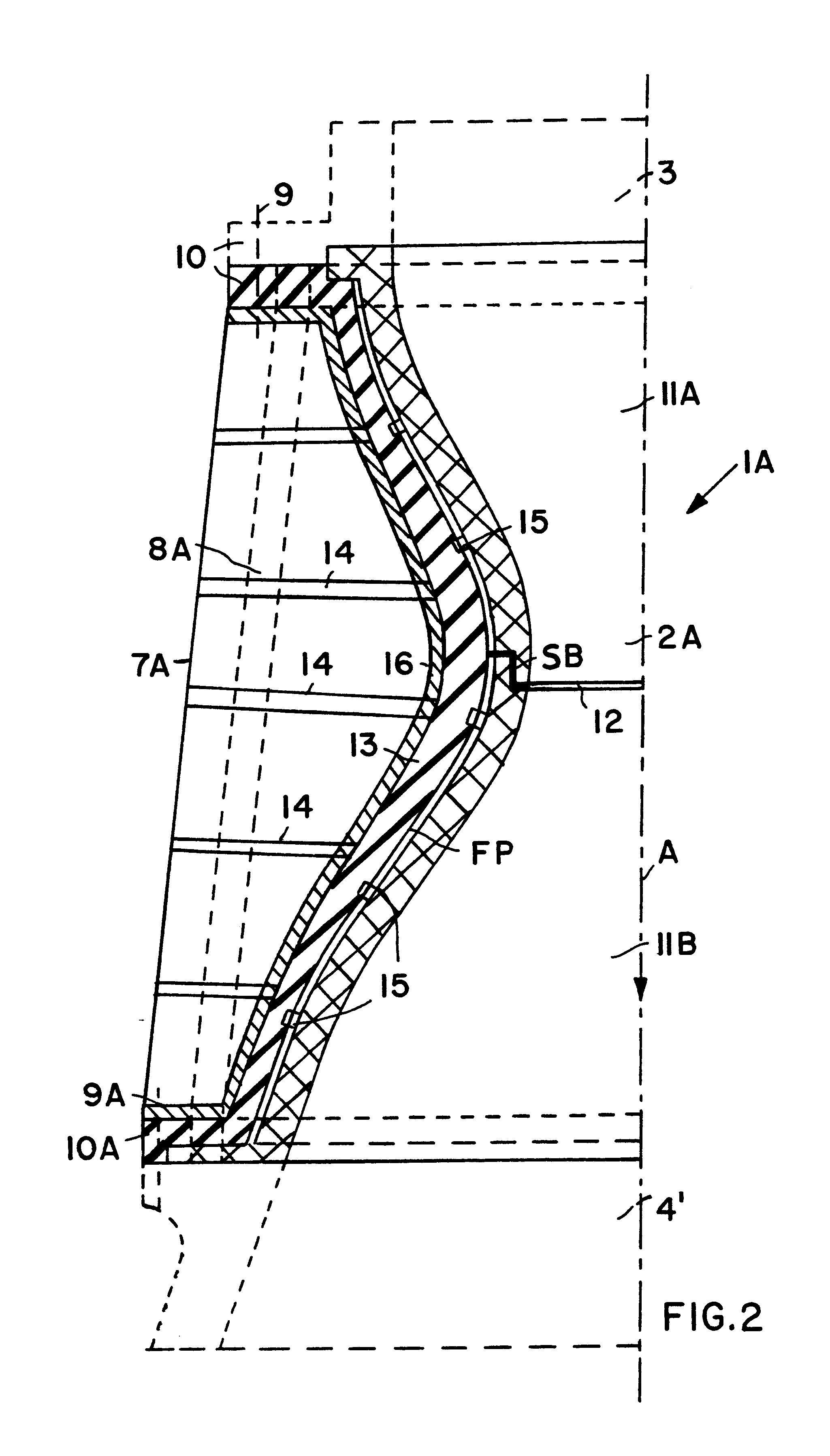
FIG. 2 shows schematically a rocket engine body 1A made according to the invention of carbon fiber reinforced silicon carbide composite (C / SiC). The body 1A surrounds with its body sections a central longitudinal directional axis A. These sections include a combustion chamber 11A, followed by a nozzle 2A, followed in turn by an expansion chamber 11B. A single piece of C / SiC composite material forms the combustion chamber 11A and the nozzle 2A. A further single piece of C / SiC composite material forms the body section surrounding the expansion chamber 11B. These body sections are bonded to each other by a silicon layer 12 forming a siliconized bond SB. The bonding between the sections, must be formed in such a way that gases under high pressure and under high temperature operating conditions cannot permeate through the siliconized bond SB to a metallic support structure 7A having a cooling channel 8A. For this purpose the interface between the sections are formed with an axial end or ...

second embodiment

FIG. 3 shows the invention. A monolithic rocket engine body 1B of carbon fiber reinforced silicon carbide composite material encloses a combustion chamber 11A, a nozzle 2A, and a combustion gas expansion chamber 11B.

The monolithic rocket engine body 1B comprises cooling channels 18 which follow the contour of the radially inwardly facing surface of the body 1B. The cooling channels are connected to the cooling systems of the fuel injection head 3 and of the combustion gas expansion chamber extension 4'. These cooling systems are not shown since they are conventional.

The monolithic rocket engine body lB has an integral insulation section 17 that may also be provided with cooling channels 18A connected to cooling channels 18 and the above mentioned conventional cooling systems of the head 3 and extension 4'. The porosity of the monolithic body 1B of C / SiC composite material may diminish radially outwardly from the wall toward a metal support structure constructed in FIG. 3 to have at ...


PUM

PropertyMeasurementUnit
Fractionaaaaaaaaaa
Linear densityaaaaaaaaaa

Abstract

A rocket engine has a combustion chamber and an expansion chamber interconnected by a nozzle. Both chambers and the nozzle are made of carbon fiber reinforced silicon carbide formed as a monolithic rocket engine body or formed in sections bonded to each other to also form such a monolithic rocket engine body. The rocket engine body is mounted in a support structure, preferably made of a metal. The rocket engine body sections are produced by mechanical machining of respective blanks made of C/SiC materials. Cooling channels and/or heat insulation structures are used for heat control. The insulation structures are preferably also made of C/SiC materials or of carbon fiber felts or of graphite film.

Description

The invention relates to a rocket engine with a central body enclosing a combustion chamber, a nozzle and an expansion chamber mounted in a support structure.BACKGROUND INFORMATIONIn a known rocket engine as shown in FIG. 1, a converging combustion chamber 1 and a nozzle 2 and a diverging expansion chamber 4 are positioned between a fuel injection head 3 and an expansion chamber extension 4'. The combustion chamber 1 and the nozzle 2 are the thermo-mechanically most heavily loaded components of such a rocket engine. The fuel injection head 3 injects fuels, for example hydrogen (H.sub.2) and oxygen (O.sub.2) or kerosene and nitric acid (MMH) and an oxidizer into the combustion chamber 1 for combustion. Combustion gases generated in the combustion chamber 1 converge into the nozzle 2 at very high temperatures and under very high pressures. Additionally, substantial pressure surges occur well above the normal operating conditions during certain operating ranges such as at ignition and ...

Claims


Application Information

Patent Timeline
IPC IPC(8): F02K9/97F02K9/00F23R3/00F02K9/62
CPCF02K9/97F02K9/972F23R3/007F02K9/974F05D2300/224F23M2900/05004
Inventor PAPENBURG, ULRICHBLENNINGER, ERNSTHERBIG, HENNINGLANGEL, GUENTER
Owner EADS SPACE TRANSPORTATION
Why Eureka
Try Eureka