Single element antenna apparatus

a single element antenna and antenna technology, applied in the direction of elongated active element feed, resonant antenna, antenna earthing, etc., can solve the problems of resistively loaded antennas, low directivity, lossy and inefficient,

a single element antenna and antenna technology, applied in the direction of elongated active element feed, resonant antenna, antenna earthing, etc., can solve the problems of resistively loaded antennas, low directivity, lossy and inefficient,

US6437756B1Inactive Publication Date: 2002-08-20TIME DOMAIN

Image

  • Single element antenna apparatus
  • Single element antenna apparatus
  • Single element antenna apparatus

Examples


Embodiment Construction

Overview of the Invention

The present invention will now be described more fully in detail with reference to the accompanying drawings, in which the preferred embodiments of the invention are shown. This invention should not, however, be construed as limited to the embodiments set forth herein; rather, they are provided so that this disclosure will be thorough and complete and will fully convey the scope of the invention to those skilled in art. Like numbers refer to like elements throughout.

Impulse Radio Basics

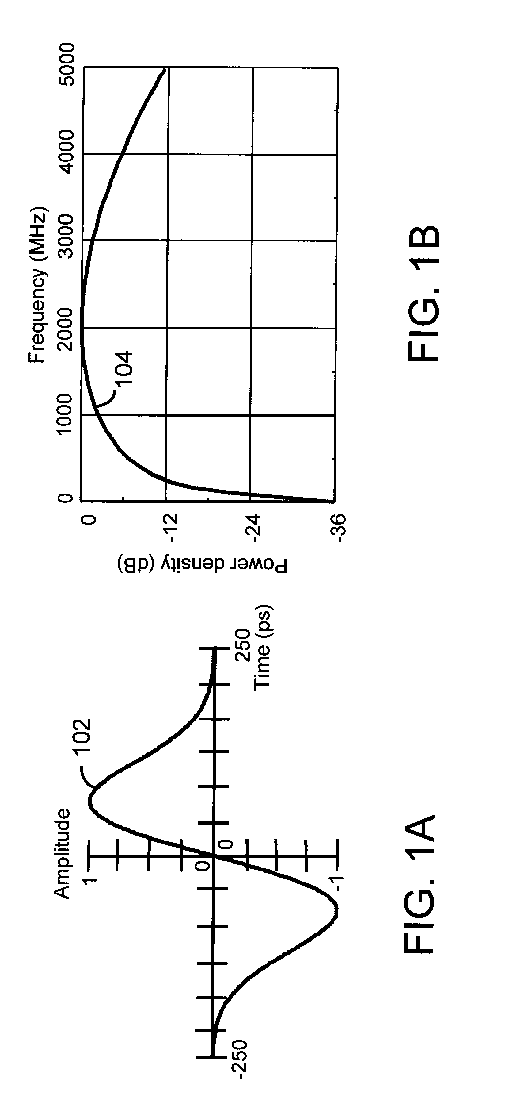
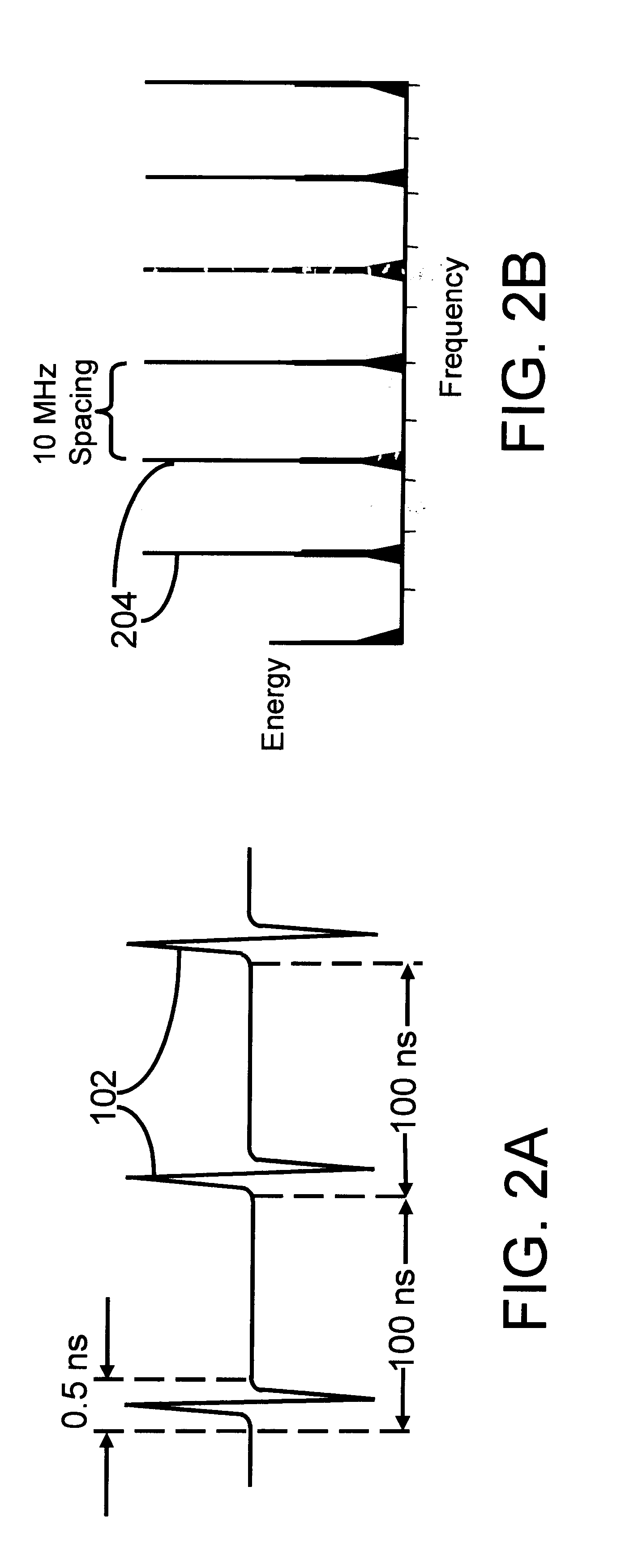
This section is directed to technology basics and provides the reader with an introduction to impulse radio concepts, as well as other relevant aspects of communications theory. This section includes subsections relating to waveforms, pulse trains, coding for energy smoothing and channelization, modulation, reception and demodulation, interference resistance, processing gain, capacity, multipath and propagation, distance measurement, and qualitative and quantitative characteri...


PUM


Abstract

An antenna for transferring electromagnetic energy includes: (a) a ground element in a ground plane; (b) a transceiver element in a transceiver plane that intersects the ground element at a first end in a joint having a first terminus and a second terminus; and (c) a feed structure that conveys the electromagnetic energy intermediate the transceiver and the host device. A first transceiver edge departs from the joint in a first path in a first direction. A second transceiver edge departs from the joint in a second path in the first direction. Each edge includes at least a first edge sector having a first radius and a second edge sector having a second radius. The radii define a separation between the edge sectors. The first and second edge terminate in a terminal structure at a second end that is spaced from the ground element to establish a gap.

Description

1. Field of the InventionThe present invention relates generally to electromagnetic energy radiation and reception using a single element antenna, and especially relates to electromagnetic energy radiation and reception with a single element antenna effected using impulse radio energy. Still more particularly the present invention provides a single element antenna suited for broadband energy radiation and reception, and particularly well suited for broadband energy radiation and reception employing impulse radio energy.2. Related ArtRecent advances in communications technology have enabled an emerging revolutionary ultra wideband technology (UWB) called impulse radio communications systems (hereinafter called impulse radio).Impulse radio was first fully described in a series of patents, including U.S. Pat. No. 4,641,317 (issued Feb. 3, 1987), U.S. Pat. No. 4,813,057 (issued Mar. 14, 1989), U.S. Pat. No. 4,979,186 (issued Dec. 18, 1990) and U.S. Pat. No. 5,363,108 (issued Nov. 8, 199...

Claims


Application Information

Patent Timeline
20 Aug 2002
Publication
US6437756B1
IPC
H01Q9/43; H01Q9/04; H01Q7/00; H01Q9/42
CPC
H01Q7/00; H01Q9/42; H01Q9/43; H04B2001/6908
Inventors
SCHANTZ, HANS GREGORY