Illuminator for macro inspection, macro inspecting apparatus and macro inspecting method

a macro inspection and microscope technology, applied in the field of photolithographic process, can solve the problems of resist pattern deformation, multi-lot loss, and microscopic detection, and achieve the effect of reducing the number of lots

Inactive Publication Date: 2002-09-17
IBM CORP
View PDF3 Cites 29 Cited by
  • Summary
  • Abstract
  • Description
  • Claims
  • Application Information

AI Technical Summary

Problems solved by technology

This is because the visual inspection (macro inspection) can detect deformations of resist patterns due to defocusing, which cannot be microscopically detected in the size measurement or overlay measurement.
Such defocusing may be caused by foreign particles adhered onto the surface of a substrate such as a wafer, distortion or deficiencies such as scratches on the surface of the substrate, the difference in resist thickness applied on the surface of a substrate, and the like, which leads to the deformation of resist patterns.
On the contrary, if visual inspection is not sufficiently effective, detection delay may cause unrenewable yielding loss over several lots.
However, it has also been quite difficult to detect defocusing.
However, since there are only slight differences in color and brightness between diffracted radiation, the difference between them is hard to discern.
Thus, visual inspection has so far required much time and experience.
However, conventional halogen lamps are used in these apparatuses, so that light diffracted by a normal position cannot be clearly distinguished from light diffracted by a deformed position.
Accordingly, even if light of a predetermined range of wavelength is separated from the diffracted light and then converted into electrical signal by an optoelectronic transducer, detection within a high degree of accuracy cannot be achieved because only a slight difference has to be detected.
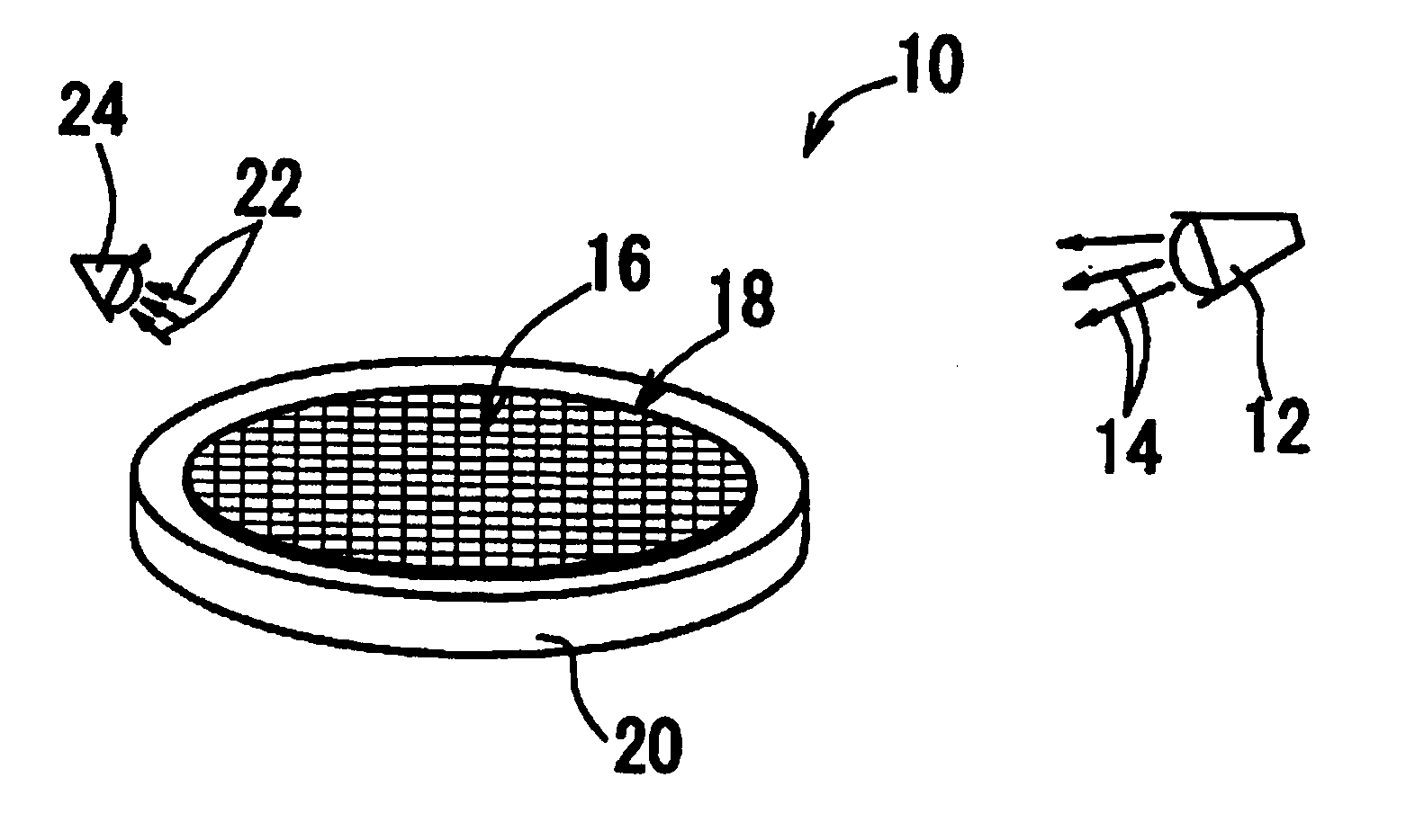
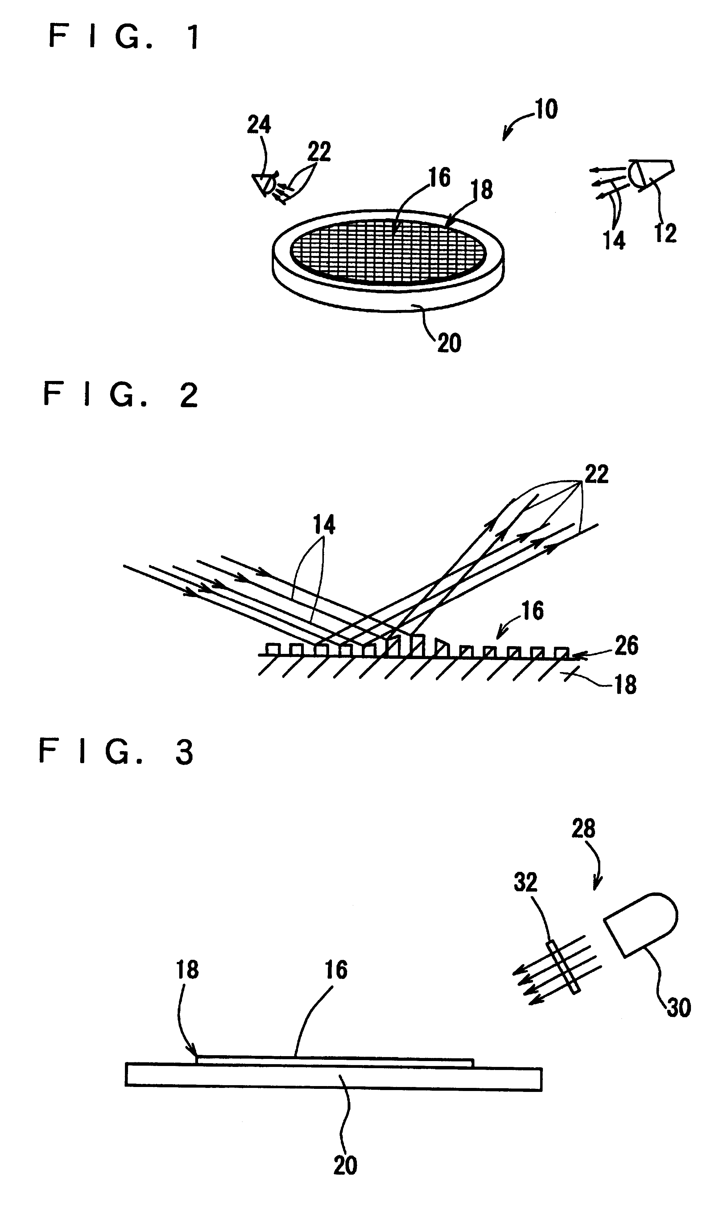
Moreover, the illuminator 12 applies the light to a limited part in this case, which makes it difficult to visually inspect the surface of the substrate for deformed parts.

Method used


Image

  • Illuminator for macro inspection, macro inspecting apparatus and macro inspecting method
  • Illuminator for macro inspection, macro inspecting apparatus and macro inspecting method
  • Illuminator for macro inspection, macro inspecting apparatus and macro inspecting method

Examples


example 1

First, a light source which is suitably used for visual inspection for defocused parts was selected. Since the intensity that human can perceive is an integral value obtained by spectral luminance efficiency shown in FIG. 8 and spectral characteristic of the light source, attention was directed to red (677 nm) and blue green (495 nm), which are complementary to each other within a wavelength range necessary for visual inspection. The contrast effect of these complementary colors is the highest when brightnesses of these two colors are equal. (Kirschman's law) Metal halide, halogen, and xenon lamps are tested by using a spectrum of each lamp to determine which lamp is the most suitable as a light source for equalizing lightnesses of red light and blue green light. The results showed that the halogen lamp having a color temperature of 2200K was the most suitable light source.

example 2

In this embodiment, visual inspections for defocused parts were conducted by using a halogen lamp (AC100V-200 W) having a color temperature of 3050K and three filters of red, green and yellow (red and green) which have spectral distributions shown in FIG. 9, and results of the inspections were compared. The illuminances on the wafer were equally adjusted by using an ND (neutral density) filter. The wafer was slightly tilted with respect to a photomask with a pitch of 0.88 .mu.m and exposed to light to form defocused parts on it.

The result showed that a synergistic effect of contrast between normal parts and deformed parts (a visible difference in the intensity of diffracted radiation) and color difference (difference in frequency between red light diffracted by the normal part and blue green light diffracted by the deformed parts, or vise versa) made it possible to clearly observe defocused parts of resist patterns having a pitch of 0.88 .mu.m (in a range of -0.05 .mu.m to +0.05 .mu...

example 3

Quantitative tests were conducted to determine how much amount of the change in resist patterns (namely, how much amount of defocused patterns) is necessary to conduct a visual inspection. In the tests, a test pattern with a pitch of 0.8 .mu.m, which is considered to be equivalent to a uniform diffraction grating, was used to form a normal wafer and a wafer containing defocused parts by increasing the level of a stage to +0.7 .mu.m and to +1.4 .mu.m with reference to the level of the stage where correct focus was obtained by a focus offset function of the stepper. The visual inspections were conducted by using a halogen lamp having a color temperature of 3050K and comprising a mirror-finished reflector, two flat convex lenses, an illumination system aperture, and a broad band yellow filter which cuts a wavelength of 520 nm or less.

Luminances and chromaticities of normal parts (+0.7 .mu.m) and deformed parts (+1.4 .mu.m) were measured using TOPCON BM-5A luminance meter. Results of me...


PUM

PropertyMeasurementUnit
wavelengthaaaaaaaaaa
color temperatureaaaaaaaaaa

Abstract

The inspecting apparatus according to the present invention includes an illuminator for emitting radiation onto a substrate having a surface on which a fine feature pattern is formed. Inspection for defects in the pattern is performed by visually inspecting radiation diffracted by the surface. The illuminator provides radiation including two different complementary colors.

Description

The present invention relates to an illuminator for macro inspection, a macro inspecting apparatus, and a macro inspecting method. More particularly to an illuminator, an inspecting apparatus, and an inspecting method which are suitable for not only inspecting dust and scratches on the surface of a wafer, but also visually inspecting the presence or absence of deformed parts caused by local defocusing on the surface of a wafer, which is finely patterned by a photolithographic method.DESCRIPTION OF RELATED ARTIn a photolithographic process for producing a semiconductor device, various factors such as line width and superposition have to be controlled. In addition, other factors such as resist thickness also have to be controlled so as not to cause defocusing. In order to control these factors, visual inspection for defocusing, size measurement, and overlay measurement are conducted as an in-line inspection of a wafer after resist pattern is formed by each photomask. Generally, in siz...

Claims


Application Information

Patent Timeline
Patent Type & Authority Patents(United States)
IPC IPC(8): G01N21/956G01N21/88G01B11/24G01B11/30G01N21/84H01L21/027H01L21/66
CPCG01N21/956
Inventor UDA, MITSURUYAMAGUCHI, TSUYOSHISHINOHARA, MASAMI
Owner IBM CORP
Why Eureka
Try Eureka