Method of fabricating silicon capacitive sensor

a capacitive sensor and silicon technology, applied in the field of fabricating silicon capacitive sensors, can solve the problems of small environmentally-caused capacitance changes over time, small environmental impact changes, and insignificant changes, and achieve the effects of reducing the conductivity of the substrate 102, reducing the stray capacitance in the sfb tmcps, and minimizing the bonding area

Inactive Publication Date: 2002-10-15
CASE WESTERN RESERVE UNIV
View PDF22 Cites 144 Cited by
  • Summary
  • Abstract
  • Description
  • Claims
  • Application Information

AI Technical Summary

Benefits of technology

It is an object of this invention to provide a force sensor and a manufacturing method for a force sensor (such as a capacitive pressure sensor) which has long term stability, and good linear sensitivity, even in harsh environments, both in operation and in OEM application of the sensor in manufactured goods, e.g., such as building the sensor into the rubber of a pneumatic tire, and utilizing the sensor during operation of the tire.
Another approach to dealing with stray capacitance involves the use of reference capacitors to attempt to null out the zero pressure capacitance. In much of the prior art, the reference capacitor has been included in the interface circuits, but this can require complex circuitry and even then may not assure that the reference capacitor in the interface circuit changes with ambient conditions in the same way as the stray capacitance in the sensor. These problems are avoided when the reference capacitor is formed on the same silicon chip as the sensing capacitor and its accompanying stray capacitance. An advantageous feature of this invention is sensor designs which enable the implementation of a reference capacitor (e.g., 141, 241) on the same silicon chip (e.g., 100, 200) as the sensing capacitor (e.g., 140, 240).

Problems solved by technology

Therefore, small environmentally-caused capacitance changes over time become insignificant and can be neglected.
Drift exhibited by silicon-to-glass capacitive pressure sensors is believed to be caused by mismatch between the thermal expansion coefficients of the glass and the silicon, and the stress built during fabrication.
Other problems can arise under temperature extremes which may cause the glass or glass frit to outgas.
A limitation of this technique is that the surfaces to be bonded must be microscopically smooth in order to achieve the intimate contact needed to form good silicon-to-silicon or silicon-to-silicon oxide fusion bonds.
As such, the sensor cannot function in a touch mode since ambient pressure deflects the diaphragm away from the fixed electrode.
Among the problems inherent in this design are the expense of a relatively complicated process and "stray capacitance" effects.
Unfortunately, ion bombardment doping is much more time consuming, and therefore more expensive, than diffusion doping.
Problems with capacitive pressure sensors can arise when the sensor must operate over a wide range of temperatures and over a wide range of pressures.
These characteristics are particularly important for applications such as sensors disposed inside tires, where ambient conditions vary significantly and access for maintenance and calibration is limited and relatively costly.

Method used


Image

  • Method of fabricating silicon capacitive sensor
  • Method of fabricating silicon capacitive sensor
  • Method of fabricating silicon capacitive sensor

Examples


embodiment 100

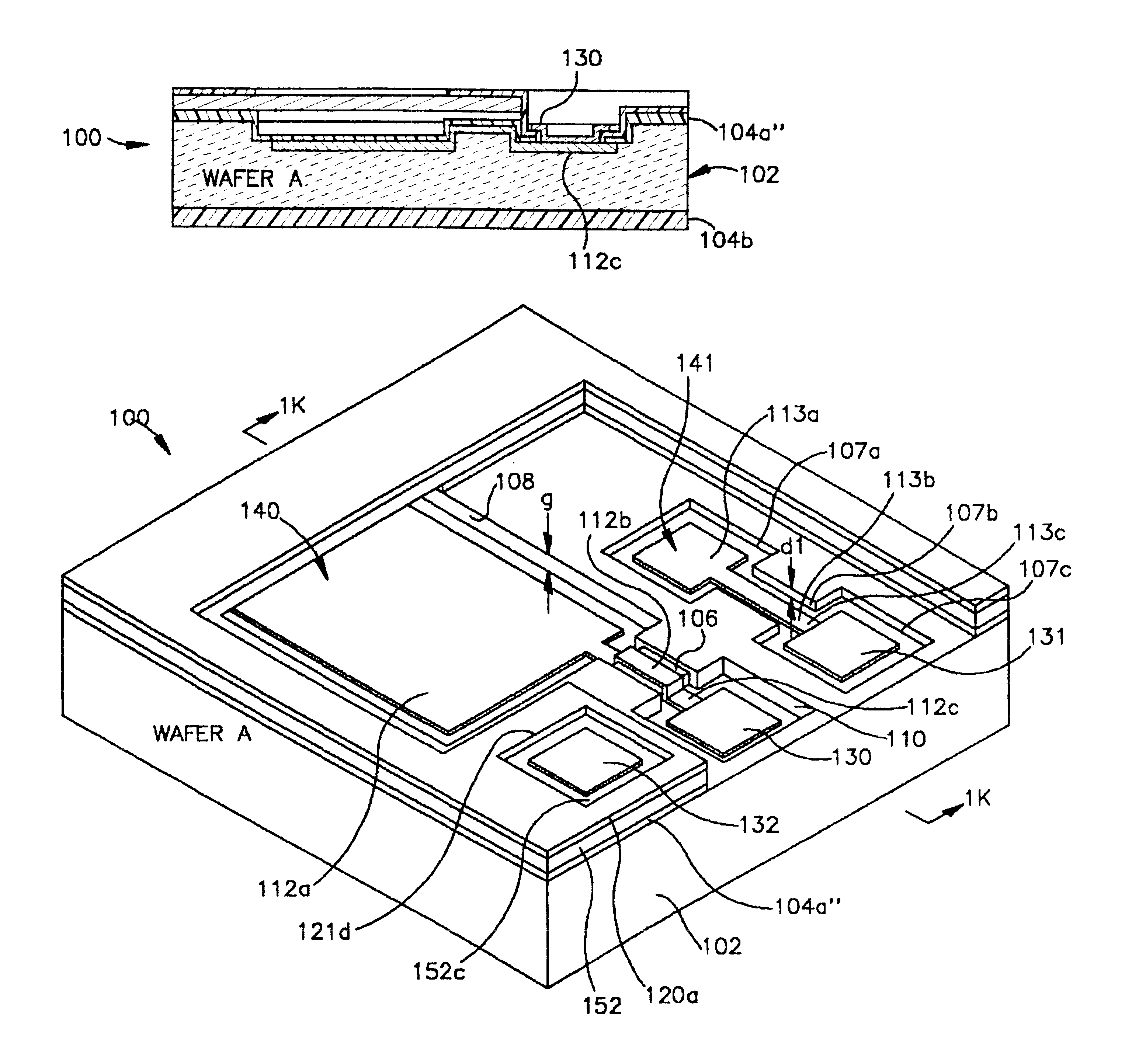
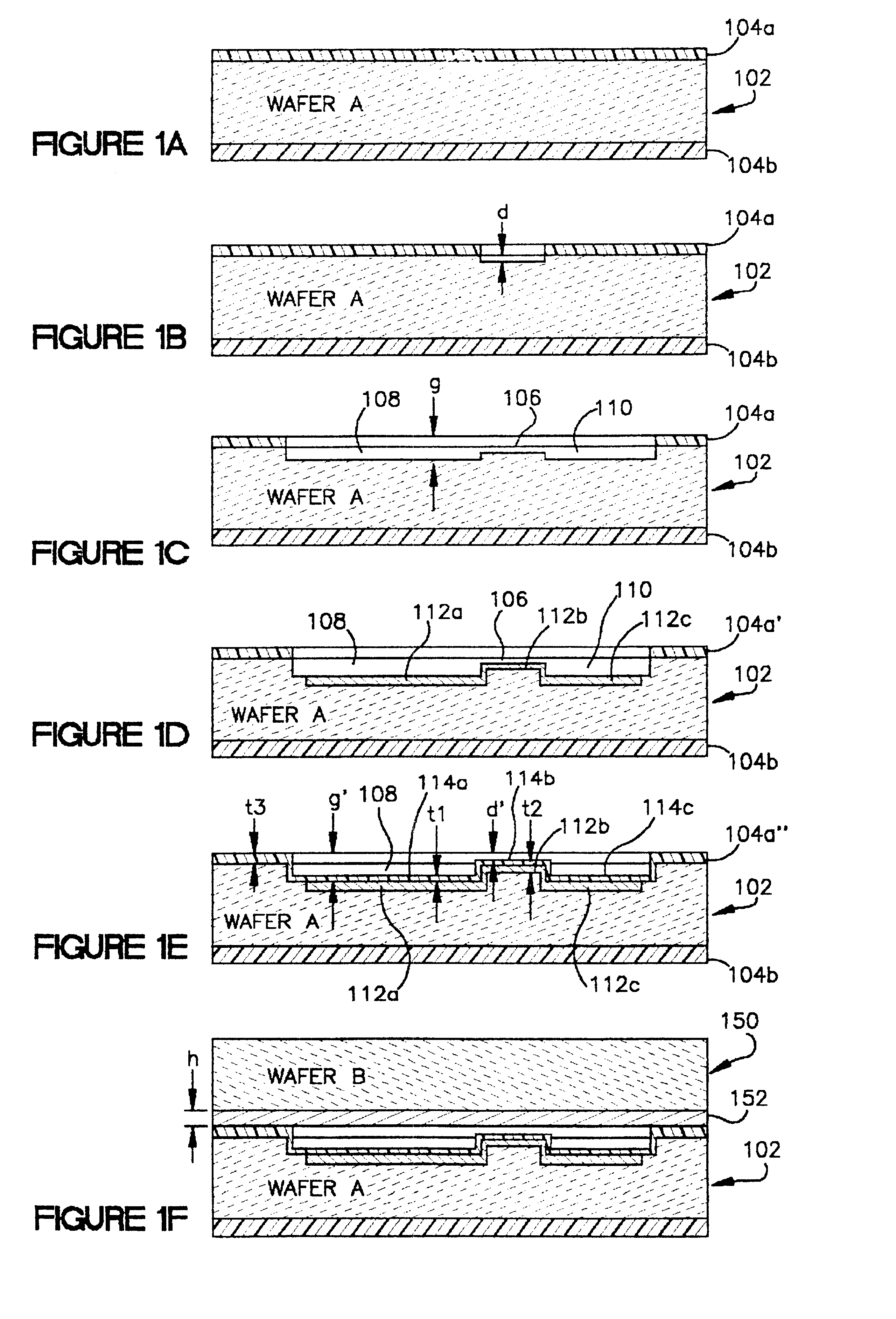
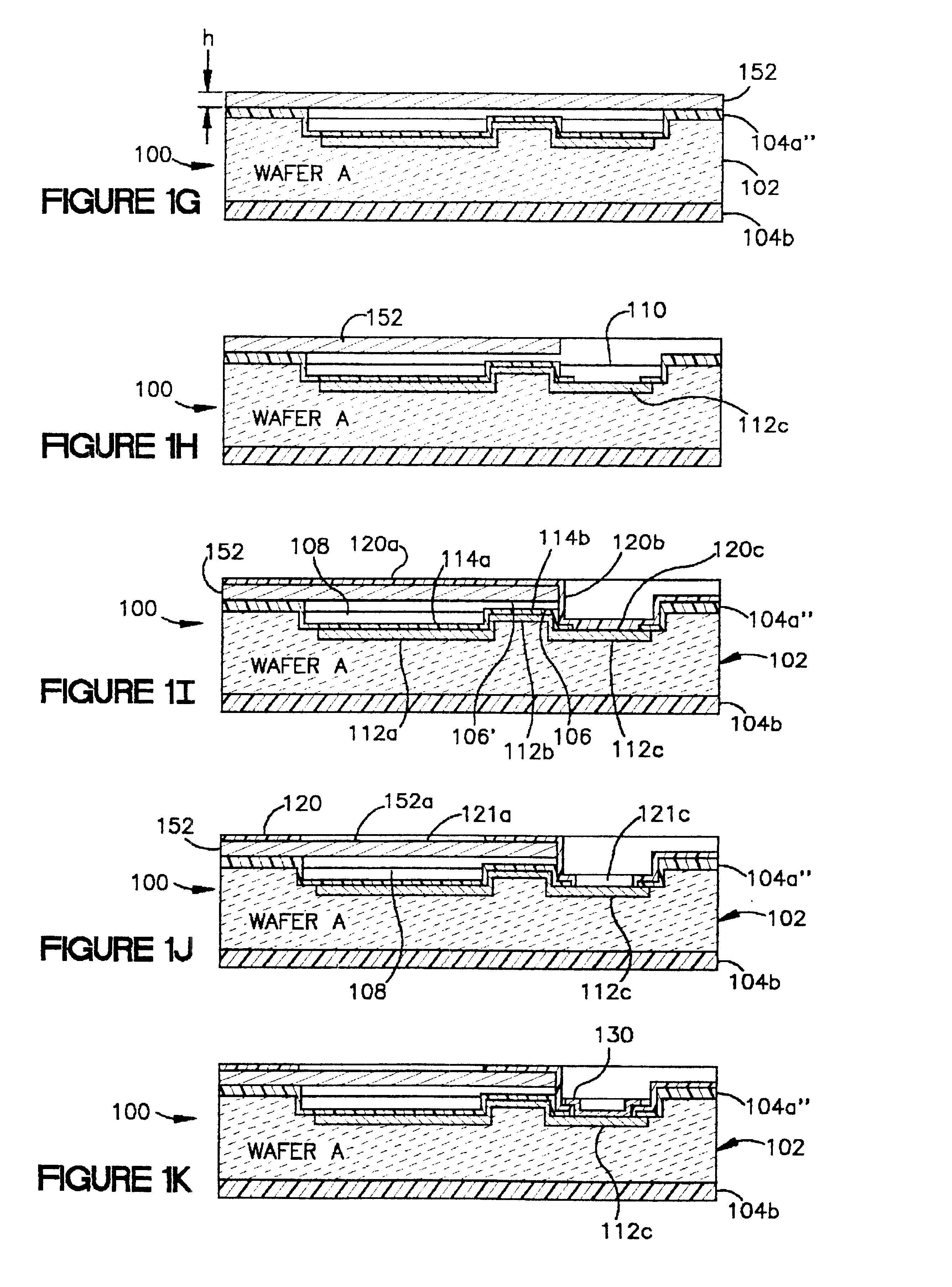
Referring to the drawings, FIGS. 1A to 1K illustrate representative steps of a first preferred embodiment 100 of a structure and manufacturing process design for a touch mode capacitive pressure sensor (TMCPS) based on silicon fusion bonding (SFB) technology. The resulting sensor 100 embodiment can be seen in FIG. 1L, shown in a partially cutaway 3D view. Although these figures illustrate a single sensor at various stages in the process, it should be understood that these process steps are applied simultaneously to all the plurality of sensors, not shown, but contained within the bounds of the same wafer assembly which contains the illustrated sensor.

A first exemplary SFB TMCPS fabrication process, for fabricating a plurality of SFB TMCPS sensors according to the invention, includes the following process steps. Although the steps are numbered for convenient reference, it is within the scope of this invention to fabricate a sensor using some or all of these steps, and in any order. I...

first embodiment

Step 4. FIG. 2C illustrates the bonded assembly of the two wafers, wafer A (202) and wafer B (250). Before bonding, the top wafer B (250) must be prepared as in the first embodiment described hereinabove: a well-defined thickness "h" of heavily doped boron (using a diffusion process) creates a P+ silicon layer 252; the now-roughened surface of the P+ layer 252 is suitably polished using chemical-mechanical polishing (CMP); and then wafer B (250) is bonded to the substrate wafer A (202) using the silicon fusion bonding (SFB) technique, with the P+ silicon diaphragm layer 252 bonded to the insulating oxide layer 204a. No alignment is required during the bonding. The bonding is performed in a vacuum in order to provide a vacuum reference in the resulting hermetically sealed sensing cavity 208.

Step 5. FIG. 2D illustrates the wafer assembly 200 after dissolving away the unwanted portion of wafer B (250). After bonding in the previous step, the wafer assembly 200 is immersed in a dopant-d...


PUM

PropertyMeasurementUnit
temperatureaaaaaaaaaa
particle sizeaaaaaaaaaa

Abstract

Manufacturing all-silicon force sensors, such as capacitive pressure sensors (100, 200) that have long term stability and good linear sensitivity, and can be built into of a pneumatic tire. The sensors include buried electrical feedthrough (112b) to provide an electrical connection into a sealed silicon cavity (108). The buried feedthrough consists of a conductor (112b) in a shallow groove (106) in a substrate (102), communicating between the sensing cavity (108) and an external contact area (110). The sensor designs also feature a method for forming a silicon-to-silicon fusion bond (SFB) wherein at least one of the two surfaces (152, 252) to be has a tough silicon surface unsuitable for good SFB joints because it was bonded heavily boron-doped by means of diffusion. The method of this invention includes preparing each doped surface (152, 252) for SFB by polishing the surface with a Chemical-Mechanical Polishing (CMP) process. The sensor designs can also include optional reference capacitors (141, 241) on the same chip (100, 200) as the sensing capacitor (140, 240). The reference capacitors (141, 241) are insensitive to pressure (force), but respond to ambient temperature changes in the same way as the sensing capacitor. Suitable external interface circuits can utilize the reference capacitors (141, 241) to pull out the majority of ambient temperature effects.

Description

The invention relates to pressure sensors and, more particularly, touch mode capacitive pressure sensors.In various industrial and commercial applications, it is desired to measure pressure in a hostile environment, with a miniaturized sensor having good stability, low power consumption, robust structure, large over pressure protection range, and good linearity and sensitivity. For example, such a sensor could be used in conjunction with an RF transponder disposed within a pneumatic tire as shown in commonly-owned, copending PCT patent application No. US98 / 07338 filed Apr. 14, 1998, incorporated in its entirety by reference herein. Applications such as the pneumatic tire place additional requirements on the pressure sensor due to the need for the sensor to withstand both the normal operating temperature and pressure ranges and also the much higher (many times the operating values) manufacturing temperature and pressure. For example, molding the sensor into a tire is but one illustra...

Claims


Application Information

Patent Timeline
Patent Type & Authority Patents(United States)
IPC IPC(8): G01L9/12H01L21/301H01L21/00H01L21/02G01D5/241H03C3/00
CPCG01D5/2417G01L9/0073G01L9/0042G01L9/125G01L17/00
Inventor KO, WEN H.WANG, QIANG
Owner CASE WESTERN RESERVE UNIV
Why Eureka
Try Eureka