Solid lubricating rolling bearing

Inactive Publication Date: 2002-10-29
NSK LTD
View PDF30 Cites 25 Cited by
  • Summary
  • Abstract
  • Description
  • Claims
  • Application Information

AI Technical Summary

Problems solved by technology

However, the solid lubricating material is extremely fragile and sometime suffers from cracking or chipping during assembling of bearings.
In the spacer type solid lubricating bearing in which the recess for the insertion of the spacer is disposed to a portion of the bearing as disclosed in the publication described above for incorporating the spacer, not only the fabrication cost increases, but also the inserted spacer is caught by the recess to hinder the rotation and, accordingly, sometimes causes abnormal vibrations.
Particularly, in a case where an axial load exerts on the bearing, since the rolling face approaches the recess, abnormal vibrations tend to be generated to bring about a problem that the spacer is dropped depending on the case.
Further, when the solid lubricating spacer is interposed between each of the rolling elements, the numbe

Method used


Image

  • Solid lubricating rolling bearing
  • Solid lubricating rolling bearing
  • Solid lubricating rolling bearing

Examples


example 1

A comparison test conducted for confirming the effect of the present invention is to be described.

Test bearings used those of bearing number 6204 both for examples and comparative examples, and used a self lubricating sintered composite material comprising 55% of a lubricant ingredient comprising molybdenum disulfide and tungsten disulfide as the main ingredient and the balance of an Fe series alloy as the material for the spacer to be incorporated.

A: Example

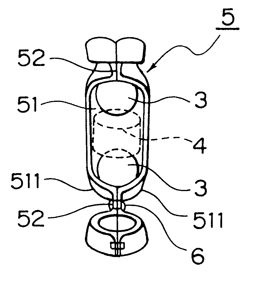
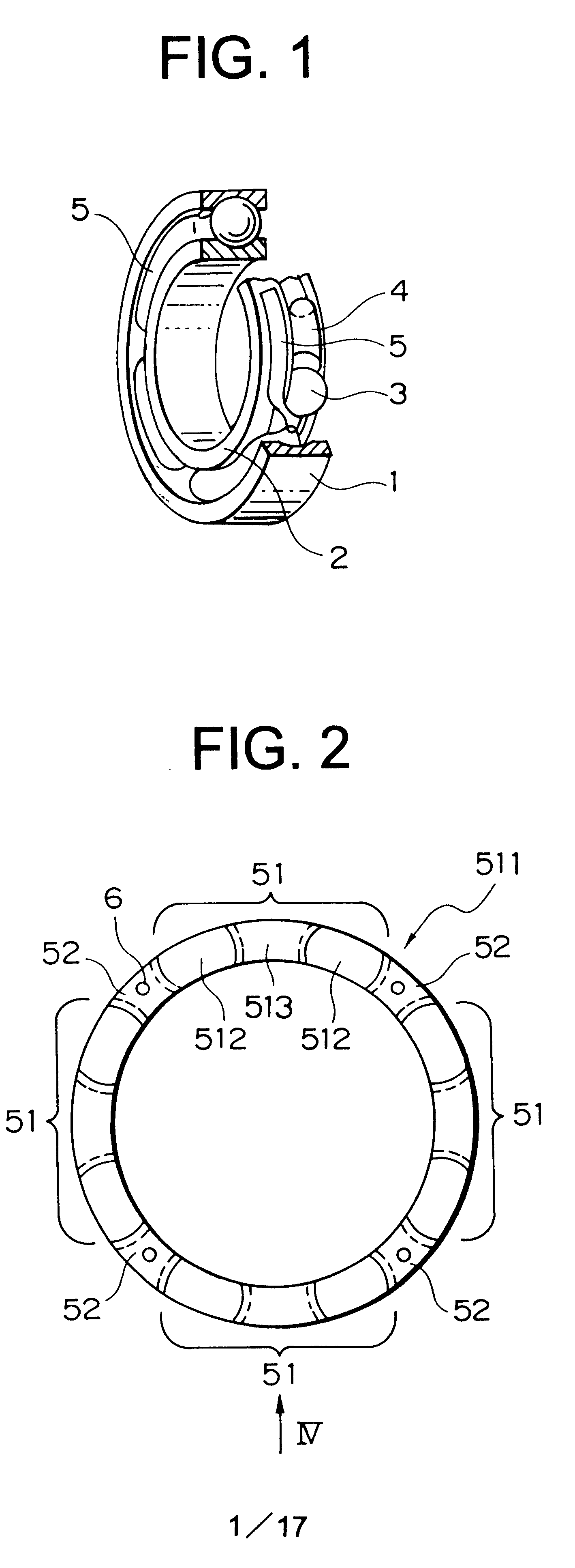
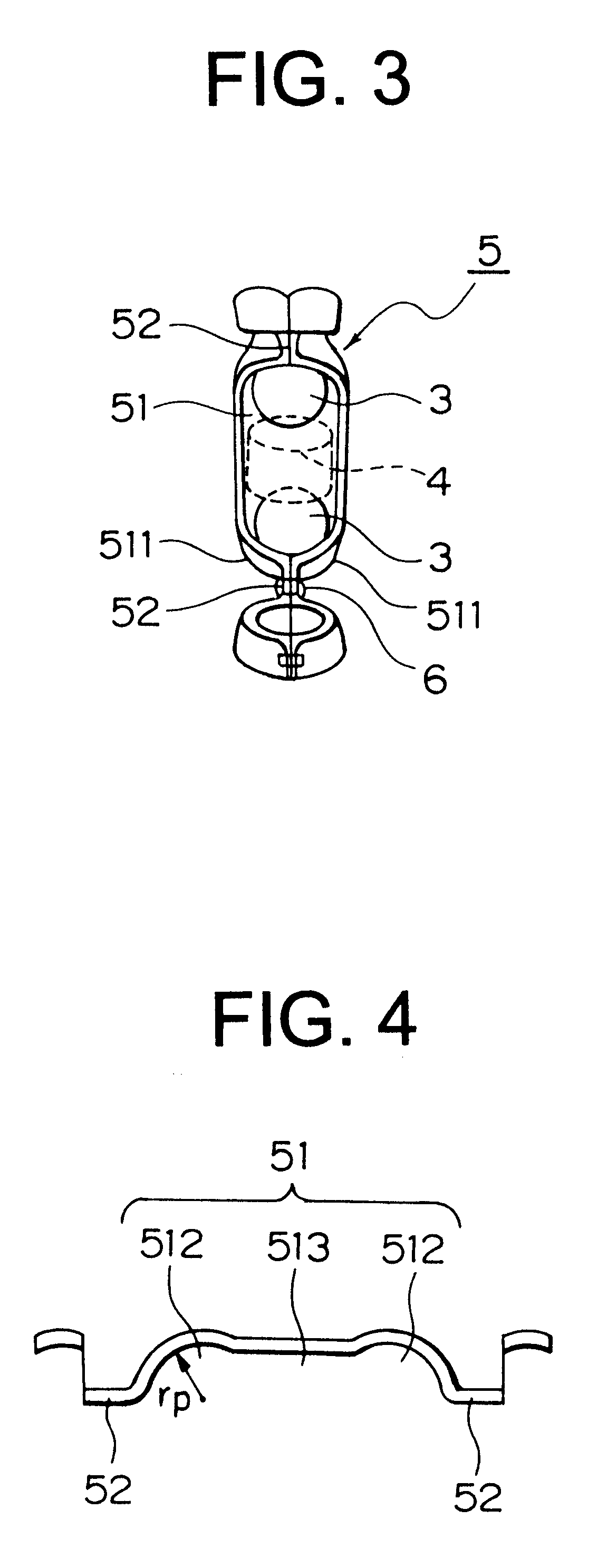
As an example, a solid lubricating deep groove ball bearing was used as an embodiment of the present invention (refer to FIG. 1-FIG. 5).

example 2

As other examples of the solid rolling lubricating bearing of the present invention, a rolling bearing of bearing number 6204 incorporated with solid lubricating spacers of the size shown in Table of FIG. 15 (bearing material: SUS 440 C for inner / outer ring, SUS 304 for cage, radial clearance: 60-100 .mu.m, material for spacer: Fe alloy+MoS.sub.2 composite material) were trially manufactured and a rotational test was conducted.

The rotational test was conducted under a radial load of 196N, a number of rotation at 100 rpm and an atmospheric temperature of 300.degree. C. and the radial vibration value and the rotational torque value during rotation were measured. The test was conducted on the standard value based on the values three times the stationary vibration value and stationary torque value in Example C-1 tested at first and the test was completed when either the vibration value or the torque value of the test bearing exceeded the standard value.

Further, for those in which the st...

examples c-1 to c-3

are products of the present invention in which the ratio of the diameter of the spacer to the rolling element diameter (ds / dw) was defined within a range from 0.89 to 0.69. In Comparative Examples D-1 and D-2, the spacer diameter was made somewhat greater than the range of the present invention in which the ratio to the diameter of the rolling element was about 0.98 to 0.96. In Comparative Example D-3, although ds / dw was at 0.6 within the range of the present invention, the circumferential clearance .delta..sub.1 of the spacer between the rolling elements was a negative value.

In Comparative Examples D-4 and D-5, the spacer diameter was made smaller than the range of the present invention and ds / dw was about 0.48 to 0.31. In the two examples, the spacer height was adjusted such that the circumferential clearance .delta.1 had no negative value.

Any of Examples C-1 to C-3 was satisfactory both in the working life and the vibrations and rotated up to 300 hrs while maintaining a low vibra...


PUM


Abstract

A spacer type solid lubricating bearing disposing a spacer comprising a solid lubricating material, for example, graphite between each of rolling elements is proposed. A solid lubricating rolling bearing is provided with an inner ring, an outer ring, rolling elements, spacers of a material containing a solid lubricant comprising a selected material, and a cage with a pocket for accommodating at least one spacer and one rolling element as a unit.

Description

The present invention relates to an improvement for a self lubrication type solid lubricating rolling bearing used under a circumstance such as at high temperature, in vacuum or at high temperature in vacuum for which grease lubrication can not be adopted.BACKGROUND OF THE ARTFor rolling bearings used under a circumstance such as at high temperature, in vacuum or at high temperature in vacuum for which grease lubrication as a general lubrication system can not be adopted, bearing lubrication of a solid lubricating system has been conducted so far. In the existent solid lubrication rolling bearing, it has been considered in an early stage to prepare a crown type cage by a solid lubricating material as a lubricant supply source. However, the solid lubricating material is extremely fragile and sometime suffers from cracking or chipping during assembling of bearings. In view of the above, a spacer type solid lubricating bearing in which a cage is separated and disposed between each of r...

Claims


Application Information

Patent Timeline
IPC IPC(8): F16C33/42F16C33/66F16C33/38F16C19/02F16C19/20F16C33/37
CPCF16C19/20F16C33/37F16C33/6696F16C33/427F16C19/06
Inventor IKEDA, NORIFUMINIZEKI, SHIN
Owner NSK LTD
Why Eureka
Try Eureka