Rotor with integrated blading

a rotor and integrated technology, applied in the direction of liquid fuel engines, marine propulsion, vessel construction, etc., can solve the problems of inability to provide the necessary emergency power of the propulsion plant, lack of ductility of the blade section of synthetic materials, and inability to meet the needs of smaller fan rotor blades operating at higher speeds

Inactive Publication Date: 2002-10-29
MTU AERO ENGINES GMBH
View PDF20 Cites 65 Cited by
  • Summary
  • Abstract
  • Description
  • Claims
  • Application Information

AI Technical Summary

Benefits of technology

The advantage results from the fact that such rotor blades, on the one hand, provide significant weight advantages over metallic blades because of the use of composite material and, on the other hand, such blades have an increased ductility and protection against erosion because of the metallic first blade section that extends along at least a portion of the leading edge of the blade and the surface area of the blade that borders on the leading edge. In addition, the present rotor blades provide a good vibration attenuation. Because of the metallic blade pan sections, the rotor blades are robust, particularly in the hub area. In the case of breakage, it is a simple matter to repair such composite material blade sections by replacing them. Based on the good damping characteristics with rotors bladed according to the invention, particularly such as compressor rotors or fan rotors, a greater fatigue notching effect resulting from defective areas that appear during operation, for example cracks, can be allowed for the present blades. Consequently, a rotor or its rotor blades according to the invention will require less frequent repair compared to conventional rotors subjected to normal wear.
Preferably, the metallic blade section forms the blade leading edge beginning radially inside at the blade root and ending a distance from the radial outer end of the blade leading edge or the blade surface. In this way, the rotor blades are protected at the flow stagnation point that occurs at the blade leading edge and at the blade surface areas next to both sides of the leading edge around which flow occurs.
Most preferably, a plurality of fan rotor blades are arranged circumferentially and equidistant from another on a compressor disk and extend essentially radially so as to form an integrally bladed compressor disk, a so-called blisk. In this case, the fan rotor blades are attached to the disk by friction welding or the like to form a single-piece component. This feature reduces the weight of the blisk, which has a positive effect on the damping, as well as the magnitude of the rotational speeds.

Problems solved by technology

The described construction, however, is not suitable for smaller fan rotor blades operating at higher circumferential speeds because they cannot withstand the prescribed load caused by a bird impact.
This hybrid construction has the disadvantage that the blade sections of synthetic material lack ductility.
As a result, too large parts of the blade sections can break off upon a bird impact so that the propulsion plant can no longer provide the necessary emergency power.
Furthermore, the retaining yoke is open toward the leading edge and the trailing edge of the blade and is torsionally soft.
Moreover, the blade section of composite material is not protected against erosion.
Such attenuation is lacking on integrally bladed rotors.
As a result, the vibrations that occur during operation and the fatigue notching effect resulting from defective points occurring on the blade section, such as cracks, present a problem.

Method used


Image

  • Rotor with integrated blading
  • Rotor with integrated blading
  • Rotor with integrated blading

Examples


Embodiment Construction

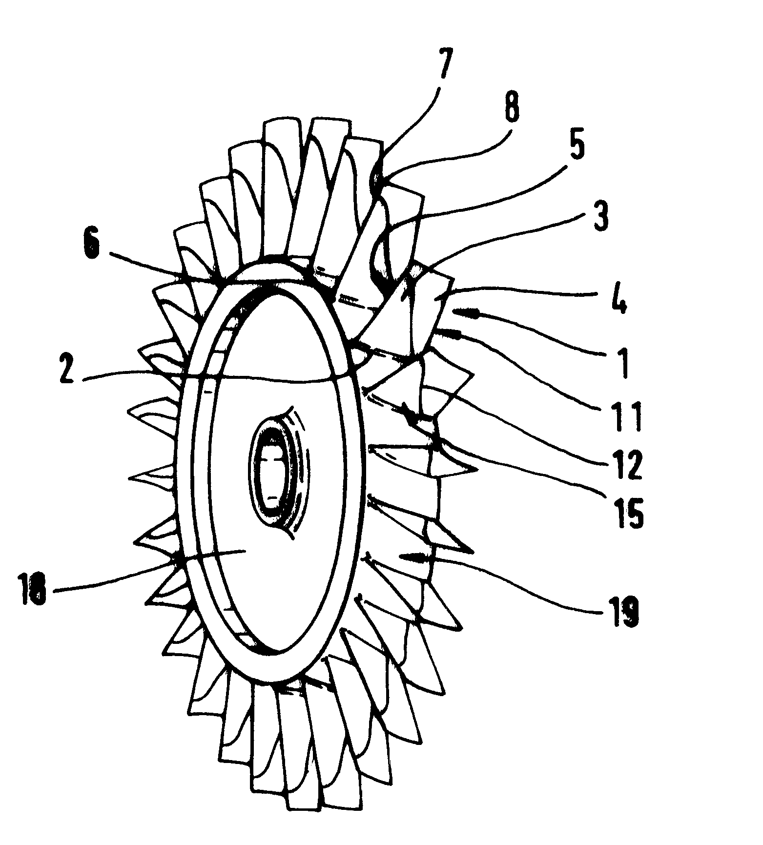
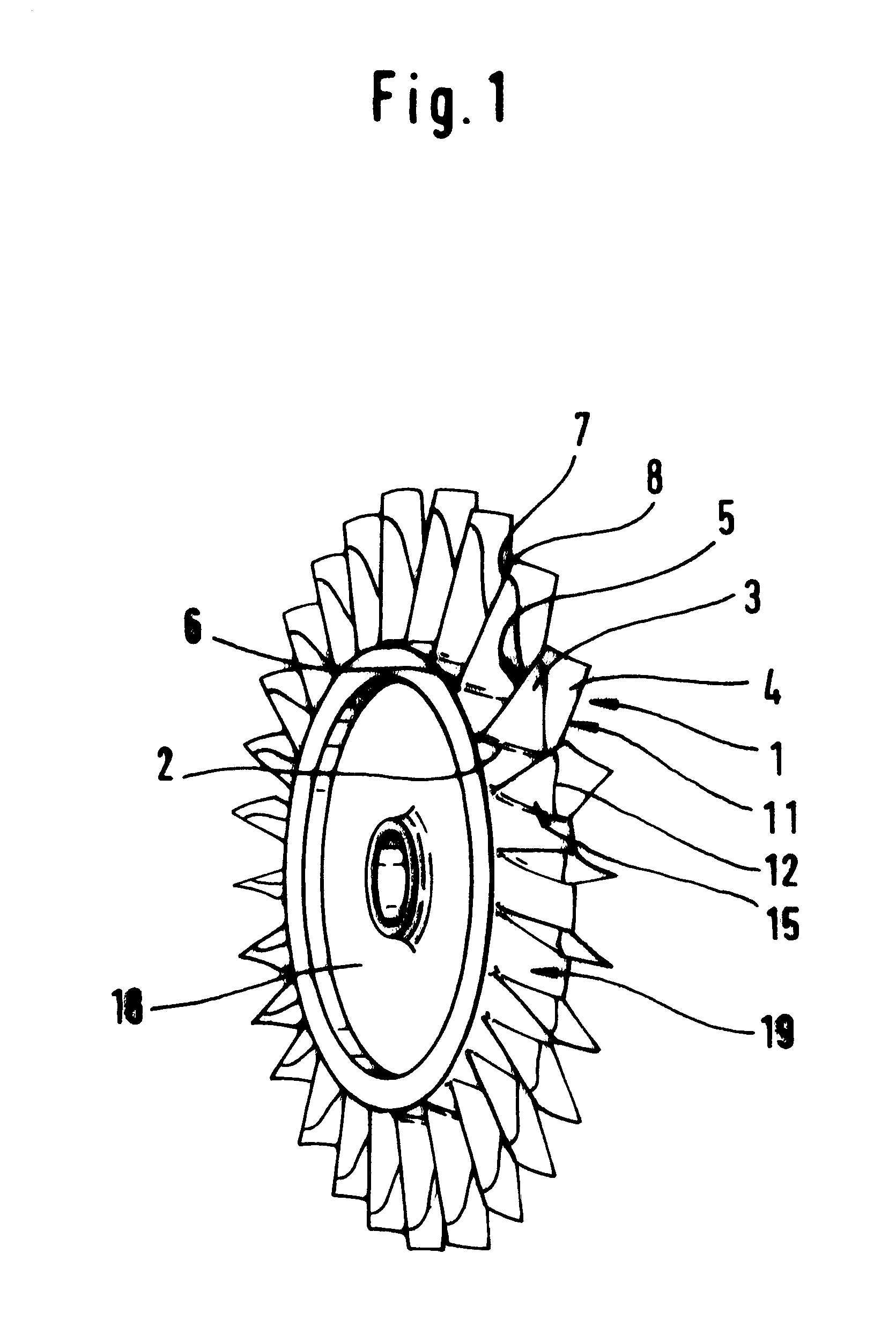
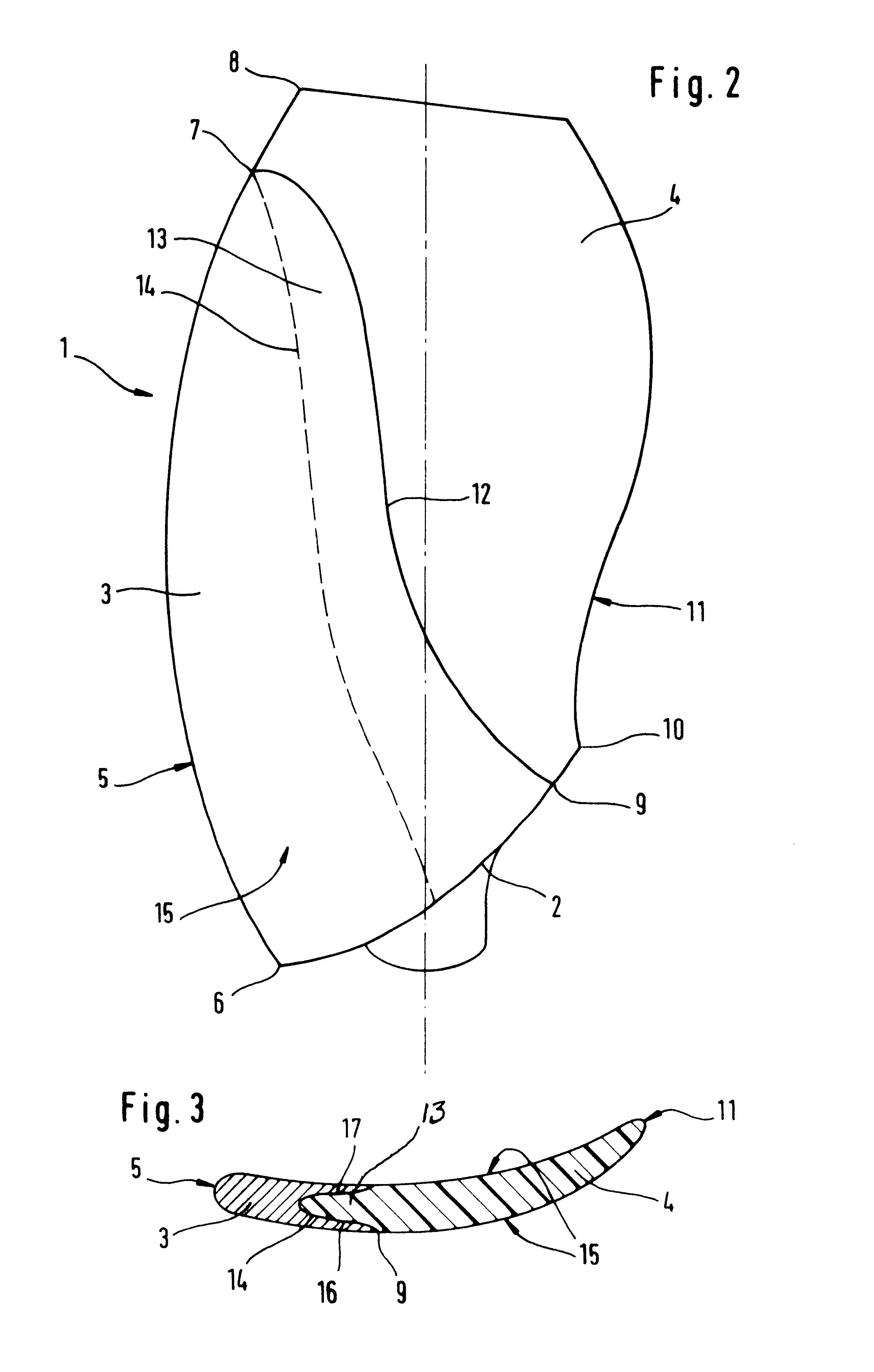
FIG. 1 shows an example embodiment of the rotor according to the invention, for example a compressor rotor, with integrated blading for a flight propulsion plant. A rotor carrier 18 is a compressor disk or ring. A plurality of rotor blades 1 is attached to a circumferential surface 19 of the rotor carrier 18. Rotor blades 1 extend essentially radially from the rotor carrier 18. The rotor blades 1 comprise respectively a metallic first blade section 3 and a second blade section 4 of fiber-reinforced synthetic material. The metallic first blade section 3 and the compressor disk 18 can, for example, be milled from a solid piece, or can be initially manufactured separately and then integrally connected to one another by a suitable method. In this context induction welding with high frequency current is a suitable choice in which a forged microstructure is formed in a joint plane between the compressor disk 18 and the rotor blade 1.

According to the embodiment shown in FIG. 1, the metalli...


PUM


Abstract

A rotor for a propulsion plant has hybrid rotor blades arranged circumferentially around and extending essentially radially from a rotor. To reduce vibrations, the rotor blade has a metallic blade root and each blade has a metallic blade section that forms at least a portion of the blade leading edge and the area of the blade surface adjacent to the blade leading edge, and a blade section made of fiber-reinforced synthetic material or composite material. The blade sections (3, 4) of each blade (1) are so correlated to each other that damage or loss of the composite material blade section (4) still enables the propulsion plant to deliver a required emergency power.

Description

The invention relates to a rotor with integrated blading, particularly for a propulsion plant. Rotor blades are arranged circumferentially around and extend essentially radially from the rotor.BACKGROUND INFORMATIONConventional fan rotor blades of fiber-reinforced synthetic material have a relatively large diameter, for example 3.2 m. Such fan rotor blades are produced as a solid construction with an integrated dovetail root or as a hollow construction with an internal piece, a so-called spar. The use of fiber-reinforced synthetic material, so-called composite material for blade sections, instead of metal, has the advantage of a substantial weight reduction. The described construction, however, is not suitable for smaller fan rotor blades operating at higher circumferential speeds because they cannot withstand the prescribed load caused by a bird impact. In order to nevertheless make use of the weight advantage, a blade section of fiber-reinforced synthetic material is attached at t...

Claims


Application Information

Patent Timeline
Patent Type & Authority Patents(United States)
IPC IPC(8): F01D5/00F01D5/28F01D5/34F01D5/14F04D29/38
CPCF01D5/147F01D5/282F01D5/34Y02T50/672F04D29/324F05D2240/303Y02T50/60
Inventor ROSSMANN, AXELSIKORSKI, SIEGFRIEDKRUEGER, WOLFGANG
Owner MTU AERO ENGINES GMBH
Why Eureka
Try Eureka