Electric arc welder for variable AC input

a technology of variable ac input and electric arc welder, which is applied in the direction of ac-ac conversion, ac-ac conversion, and conversion with intermediate conversion to dc, can solve the problems of power consumption problems of electric arc welders, power supply normally created less than 2000 watts of power, and power supply failure to meet the needs of industrial applications, etc., to achieve high output power and high power factor

Inactive Publication Date: 2003-01-07
LINCOLN GLOBAL INC
View PDF10 Cites 123 Cited by
  • Summary
  • Abstract
  • Description
  • Claims
  • Application Information

AI Technical Summary

Benefits of technology

The requirements of electric arc welding capable of converting single or three phase high voltage electrical input to a low voltage DC, with high output power for electric arc welding is accomplished by the present invention. A dual stage boost converter with a power factor correcting circuit controlled by a high speed switch provides a driven inverter network that converts rectified input voltage to an AC output in a manner still maintaining high power factor. By using a driven inverter stage at the output of the power factor correcting boost converter, a specific voltage

Problems solved by technology

These small power supplies normally created less than 2000 watts of power and were not usable for industrial applications.
In the mid 1990's, the electric arc welding industry was using inverter type power supplies with high switching frequency; however, power factor correcting technology for such power supplies did not exist.
Consequently, electric arc welders presented a problem with power consumption.
There were no techniques t

Method used


Image

  • Electric arc welder for variable AC input
  • Electric arc welder for variable AC input
  • Electric arc welder for variable AC input

Examples


Embodiment Construction

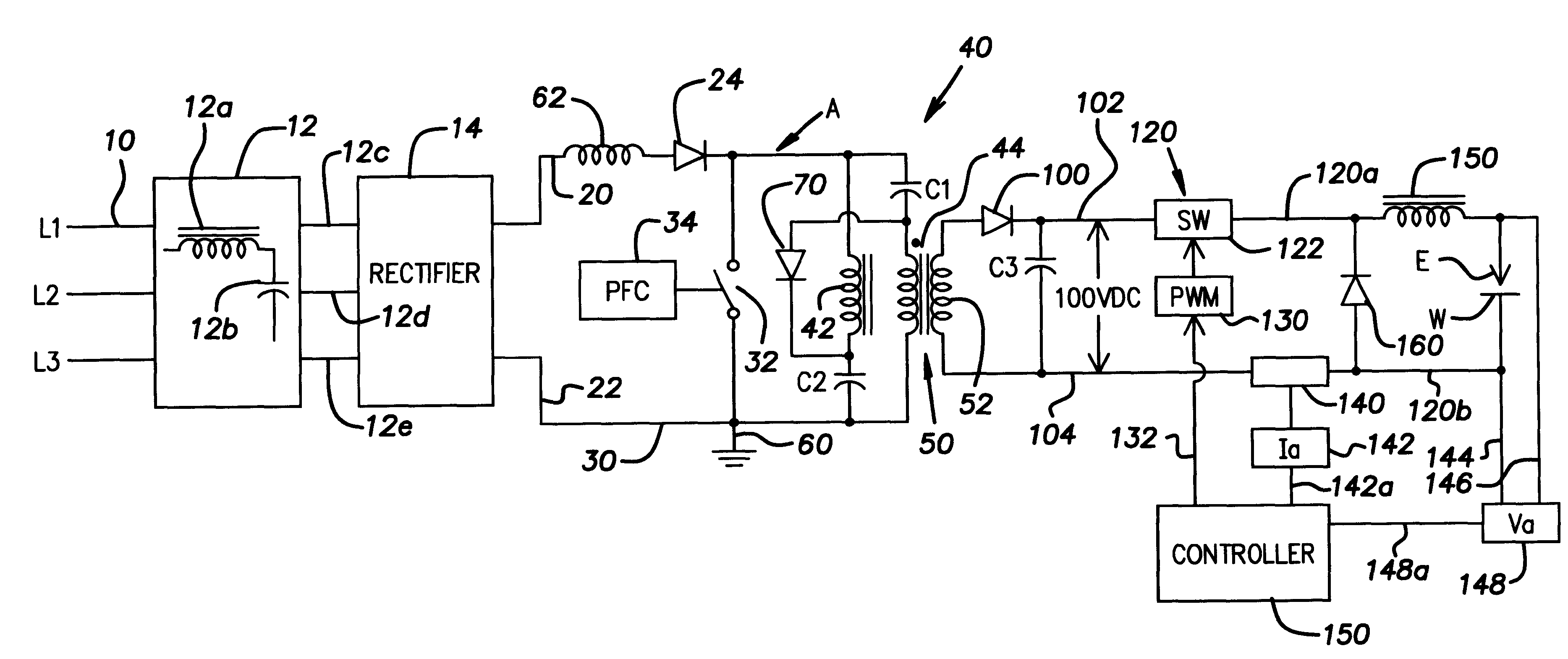
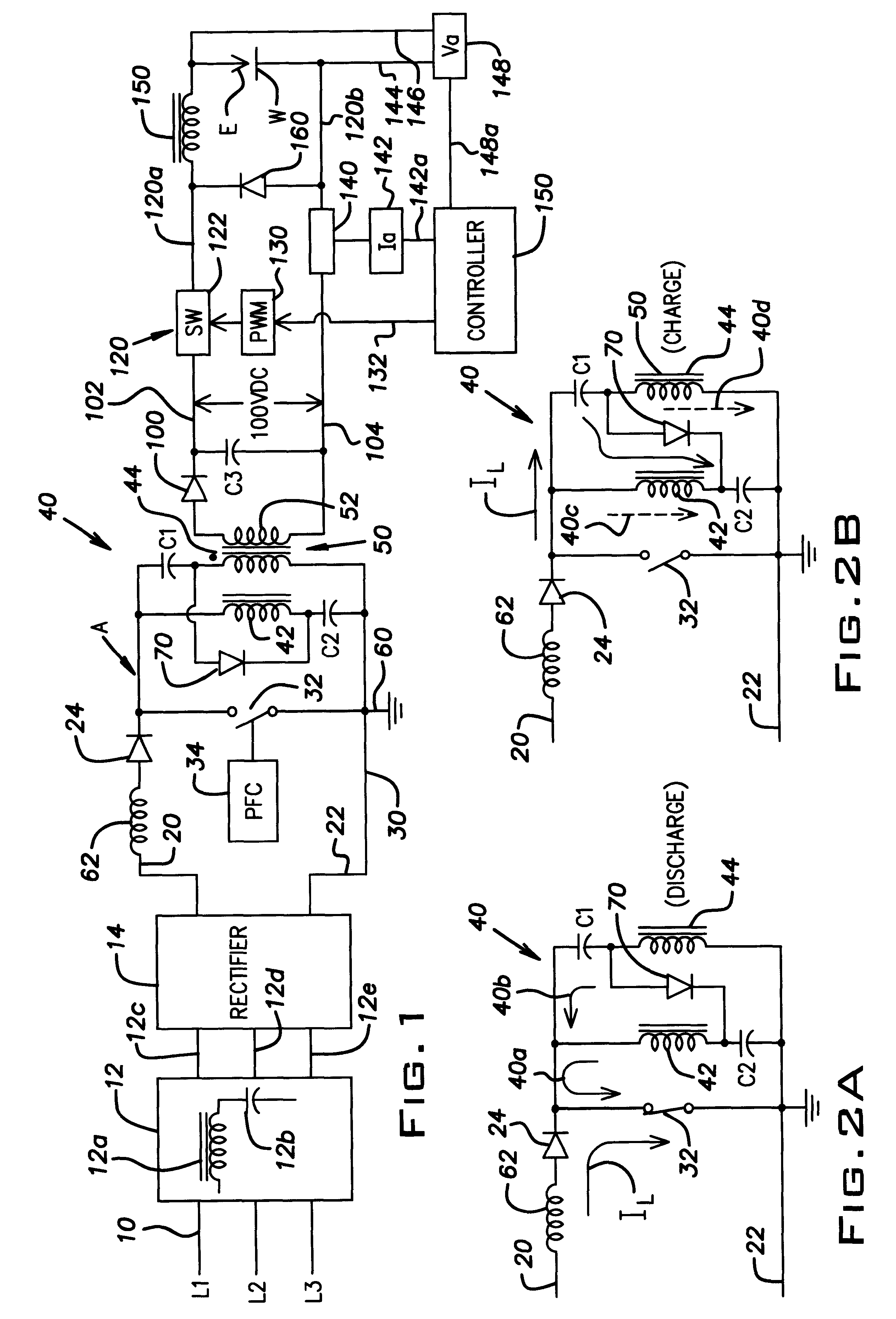
Referring now to the drawings wherein the showings are for the purpose of illustrating the preferred embodiment only and not for the purpose of limiting same, FIG. 1 shows a welder A having a universal three phase input 10 through a filter network 12 including an inductance 12a and a series of capacitors 12b with three phase AC filtered voltage on lines 12c, 12d, 12e that is directed to rectifier 14 to create a DC voltage across leads 20, 22. Diode 24 prevents reverse current flow through inductor 62. The voltage across leads 20, 22 and current in these leads is dictated by the variable input voltage in three phase input 10. A boost type power factor correcting stage 30 has an electronic switch 32 controlled by power factor correcting circuit 34. This concept is shown in Wilkinson U.S. Pat. No. 4,677,366. A commercial integrated circuit, such as Unitrode UC 3454 or UC 2852 is used for the power factor correcting circuit. The circuit is selected to cause either continuous current ope...


PUM

PropertyMeasurementUnit
Currentaaaaaaaaaa
Frequencyaaaaaaaaaa
Flow rateaaaaaaaaaa

Abstract

An electric arc welder with a variable AC voltage input of up to 600 VAC and a rectifier to provide a DC link, a driven high frequency boost stage with first and second leads connected to the DC link. The boost stage comprises an inductor, a first series output branch with a first primary winding connected to the first lead and a first capacitor connected to the second lead, a second series output branch with a second primary winding connected to the second lead and a second capacitor connected to the first lead and a high frequency operated switch between the leads and having an opened condition charging said capacitors by current through the primary windings in a first direction and discharging the inductor and a closed condition charging the inductor through the primary windings by current in a second direction and discharging the inductor to charge the capacitors. The switch is operated by a power factor control circuit at a frequency greater than about 18 kHz. The boost stage has an AC output stage comprising the secondary winding network of a transformer powered by current flow in the first and second primary windings. An output rectifier converts said AC output to a first DC voltage. At the final portion of the welder an output converter converts the first DC voltage to a second DC voltage connected across the arc of a welding station and having a controlled weld current or voltage.

Description

The invention relates to the art of electric arc welding and more particularly to an electric arc welder having a controlled voltage or current output with the variable or universal AC input that ranges up to about 600 VAC.INCORPORATION BY REFERENCEThe invention relates to a unique electric arc welder having a dual intermediate stage operated by a power factor control chip whereby a unique architecture allows the input to vary drastically up to 600 volts while the controlled output weld current and / or weld voltage is controlled in the DC welding range. By utilizing the unique architecture of the power factor control dual intermediate stage in combination with an output converter, the power supply for the electric arc welder can have high input voltage variable in magnitude with an output power exceeding two to three kilowatts. Since there are several topographies relating to this type of power supply for use in low rated appliances, several items of prior art are incorporated by ref...

Claims


Application Information

Patent Timeline
IPC IPC(8): B23K9/10B23K9/09B23K9/073H02M3/28
CPCB23K9/091B23K9/1056B23K9/1043B23K9/10
Inventor CHURCH, LARRY L.
Owner LINCOLN GLOBAL INC
Why Eureka
Try Eureka