
GaN-based high electron mobility transistor

a high electron mobility, transistor technology, applied in the direction of basic electric elements, electrical apparatus, semiconductor devices, etc., can solve the problems of dangling nitrogen atom dangle bonds, large number of lattice defects in undoped gan layers, and difficulty in high speed operation of gan-based hemt, etc., to achieve the effect of high electron mobility

Inactive Publication Date: 2003-03-18
FURUKAWA ELECTRIC CO LTD
View PDF4 Cites 55 Cited by
  • Summary
  • Abstract
  • Description
  • Claims
  • Application Information

AI Technical Summary

Benefits of technology

The solution effectively increases the electric resistivity of the undoped GaN layer, allowing for high electron mobility and realization of a pinch-off state even at zero gate bias voltage, thereby improving the operational performance of the HEMT.

Problems solved by technology

However, the HEMT using the GaAs-based compound semiconductor does not have so high dielectric-breakdown electric field value at the heterojunction interface.
Thus, the GaAs-based HEMT has difficulty in realization of high speed operation by the application of a high voltage to the gate electrode.
However, in the case of the HEMT with the above-described layered structure, usually a great number of lattice defects exist in the undoped GaN layer formed, for example, by the MOCVD method.
Particularly, a great number of lattice defects due to dangling bonds of nitrogen atoms are present.
As this kind of state lowers the electric resistivity of the undoped GaN layer, a problem arises that a pinch-off state cannot be realized even when the gate bias voltage is set at 0 V.
Thus, in the conventional GaN-based HEMTs, the n-type impurity is effectively doped in the undoped GaN layer due to the above-mentioned problems arising during the film formation process.
As a result, the undoped GaN layer cannot be given a high resistance, preventing a sufficiently high enough electron mobility and making it impossible to realize a pinch-off state even if the gate bias voltage is set at zero.

Method used


Image

  • GaN-based high electron mobility transistor
  • GaN-based high electron mobility transistor
  • GaN-based high electron mobility transistor

Examples


Embodiment Construction

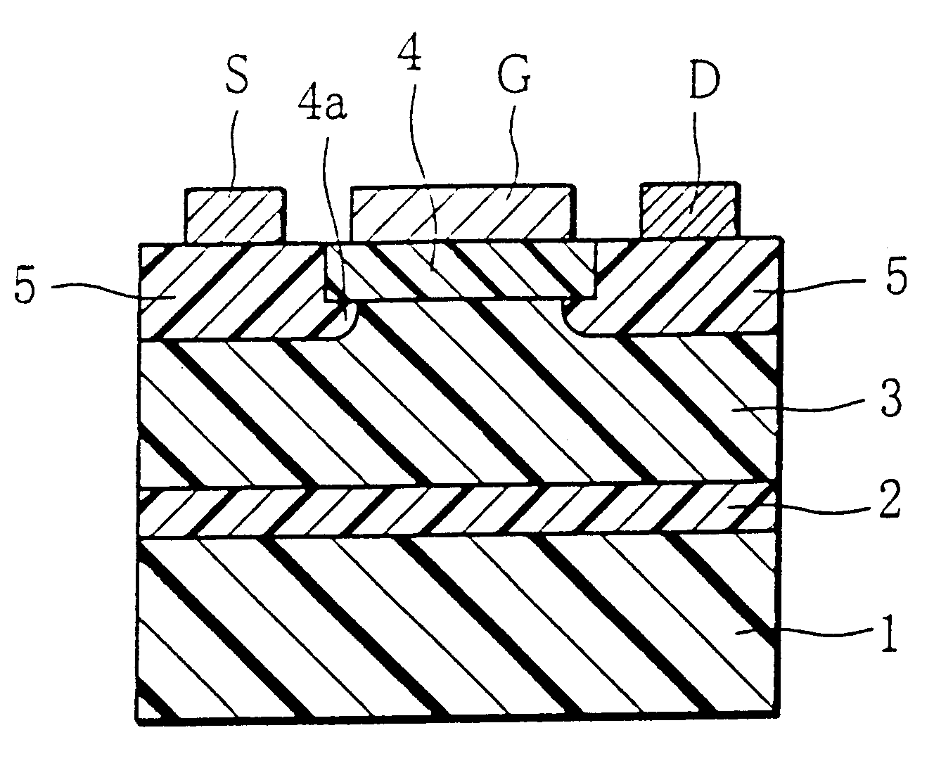
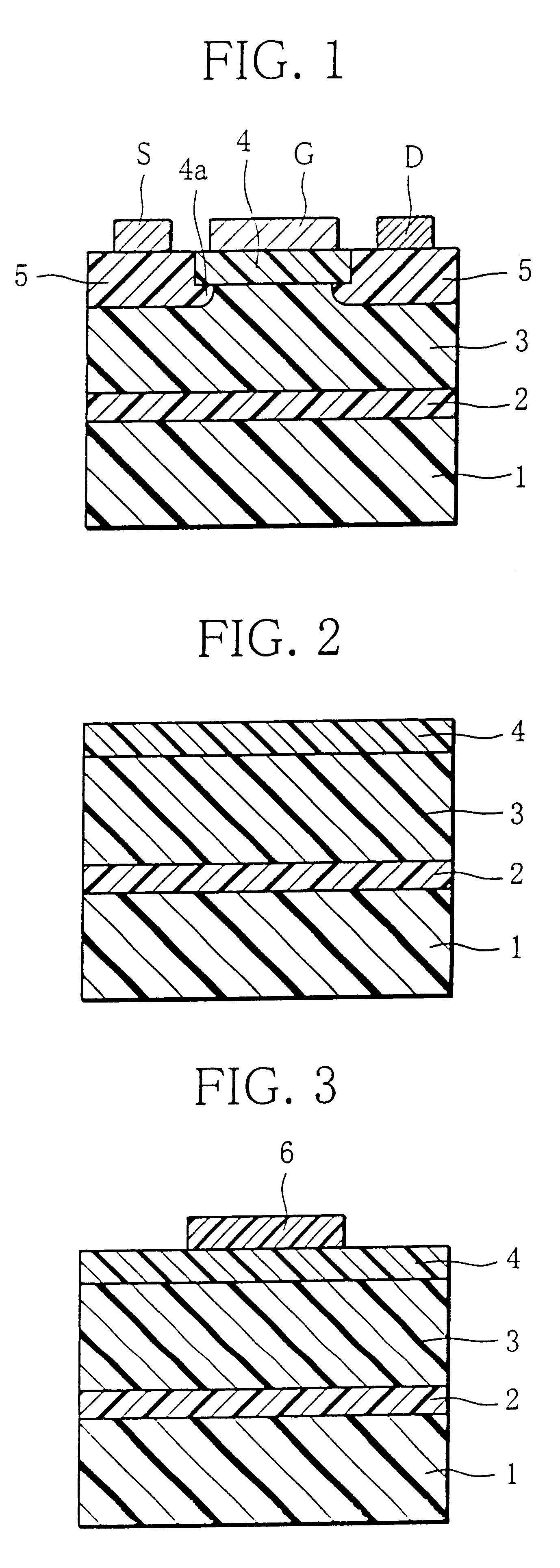
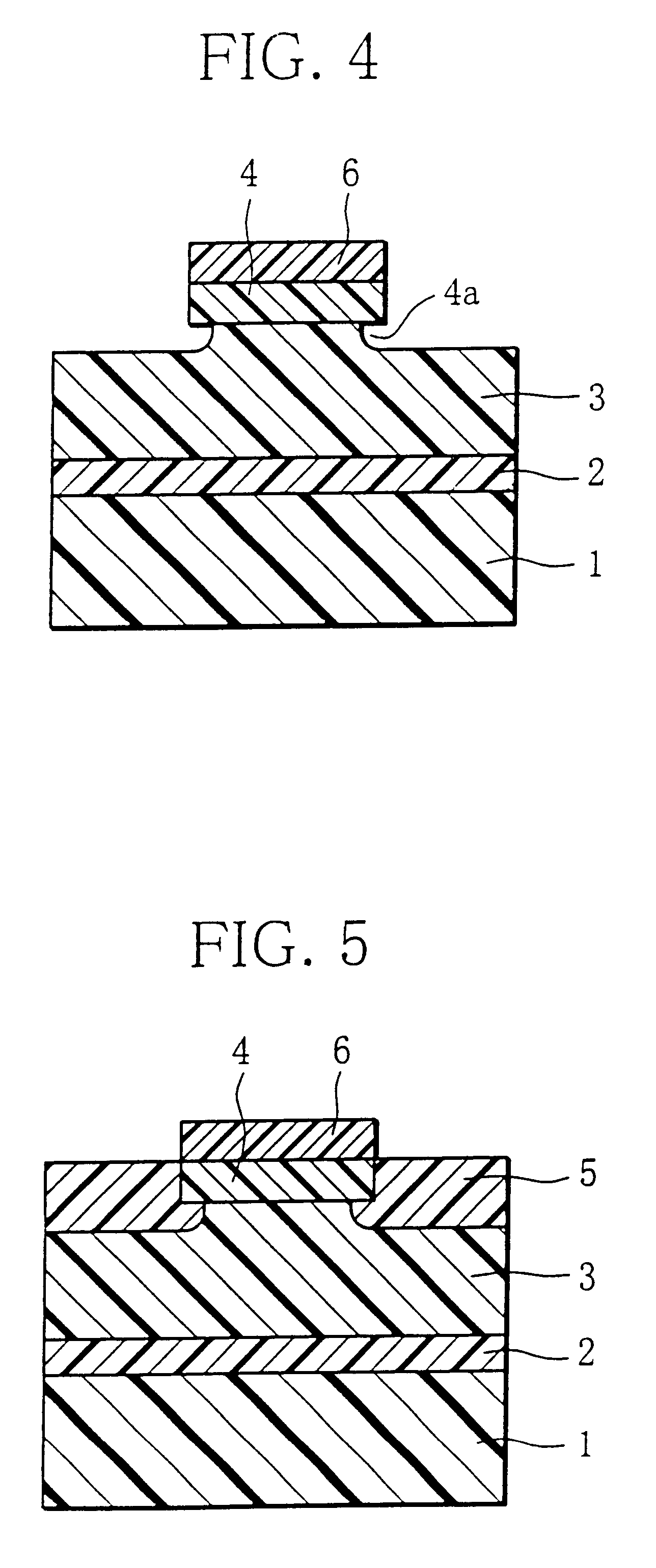
By using an ultravacuum apparatus with a growth chamber and a patterning chamber, a gas source MBE was performed to form a GaN buffer layer 2 with a thickness of 50 nm on an Si single crystal substrate 1 at a growth temperature of 640.degree. C. Metal Ga (5.times.10.sup.-7 Torr) was used as a Ga source and dimethylhydrazine (5.times.10.sup.-5 Torr) as an N source.

Then, the N source was switched to ammonia (5.times.10.sup.-5 Torr), and a gas source MBE was performed at a growth temperature of 780.degree. C., thereby forming an undoped GaN layer 3 with a thickness of 2000 nm. The carrier concentration of the undoped GaN layer 3 was controlled to 1.times.10.sup.15 cm.sup.-3 by doping a p-type impurity of Mg (1.times.10.sup.-8 Torr).

In a separate experiment, the same undoped GaN layer was formed under the same conditions. When its electric resistivity was measured by a contactless-type contact resistance measurement apparatus, the reading was 100 M.OMEGA. / cm.sup.2.

Thereafter, metal Al (...


PUM


Abstract

A GaN-based high electron mobility transistor (HEMT) has an undoped GaN layer where a two-dimensional electron gas layer is formed, the undoped GaN layer having a high electric resistivity enabling a pinch-off state to be obtained even when the gate bias voltage is 0 V. The GaN-based HEMT comprises a semi-insulating substrate on which a GaN buffer layer is formed. An undoped GaN layer is disposed on the GaN buffer layer and has an electric resistivity of not less than 1x10⁶ OMEGA / cm2. An undoped AlGaN layer is disposed on the undoped GaN layer via a heterojunction such that an undercut portion is formed therebetween. An n-type GaN layer is further disposed in such a manner as to bury side portions of the undoped AlGaN layer and the undercut portion. The individual layers thus form a layered structure. A gate electrode G is formed on the undoped AlGaN layer, and a source electrode S and a drain electrode D are formed on the n-type GaN layer.

Description

1. Field of the InventionThe present invention relates to a high electron mobility transistor (HEMT) manufactured by using a GaN-based compound semiconductor. More particularly, it relates to a GaN-based HEMT comprising an undoped GaN layer forming a channel, wherein the undoped GaN layer is highly purified or remaining n-type impurities in the GaN layer caused by lattice defects during layer formation are compensated by a p-type impurity, thereby providing the channel with a high electric resistivity and enabling a pinch-off state to be realized when the gate bias voltage is set to zero volt.2. Prior ArtThere is an expectation for the HEMT as a high-output microwave device, for example. The HEMTs are manufactured by using mainly a GaAs-based compound semiconductor today.However, the HEMT using the GaAs-based compound semiconductor does not have so high dielectric-breakdown electric field value at the heterojunction interface. Thus, the GaAs-based HEMT has difficulty in realization ...

Claims


Application Information

Patent Timeline
Patent Type & Authority Patents(United States)
IPC IPC(8): H01L29/778H01L29/66H01L29/20H01L29/02H01L21/203H01L21/338H01L29/812
CPCH01L29/7787H01L29/2003
Inventor YOSHIDA, SEIKOH
Owner FURUKAWA ELECTRIC CO LTD
Learn More