Method of joining together superconductors and a superconductor joined member produced by same

a superconductor and superconductor technology, applied in the direction of superconductor devices, manufacturing tools, solvents, etc., can solve the problems of inability to exhibit fully satisfactory performance, lack of plasticity, and inability to lead superconducting current lead wire and superconducting wire rod, etc., to achieve excellent current transmission performance

Inactive Publication Date: 2003-05-13
SUPERCONDUCTIVITY RES LAB
View PDF17 Cites 13 Cited by
  • Summary
  • Abstract
  • Description
  • Claims
  • Application Information

AI Technical Summary

Benefits of technology

Further, the above-described means of joining together oxide superconductors, capable of obtaining excellent current transmission performance can be not only applicable to production of current lead wires made up of an oxide superconductor and superconducting wire rods, but also adopted as a method of joining together oxide superconductor thick filmed wire rods (LPE wire rods), and a method of repairing a coating of members coated with an oxide superconductor film.

Problems solved by technology

However, the oxide superconductor crystal (bulk crystal), obtained by those processes described above, and so forth, has been found to be material which is brittle and lacking in plasticity, and consequently, it has been difficult to form the same into a current lead wire, wire rod, and the like, of long length, by taking advantage of plasticity.
However, since it is extremely difficult to homogenize the superconductive properties at a junction of the material, the superconductive properties at the junction becomes extremely important in the case of the superconducting current lead wires, and superconducting wire rods.
Accordingly, an oxide superconductor joined member produced by the means of joining together as described in the foregoing, interferes with transmission of superconducting current, and noticeably reduces current passing therethrough, so that a superconducting current lead wire and superconducting wire rod, produced by use of the oxide superconductor joined member, has been incapable of exhibiting fully satisfactory performance.
a) a "process of joining together oxide superconductor base materials by use of a solder of an oxide superconductor material constitution, having a melting point (peritectic point) lower than that of the oxide superconductor base materials" is a simple and stable method as means of joining together oxide superconductors, however, with this process, epitaxial growth of superconducting crystals is caused to take place from the solder in a molten state, and consequently, it is extremely difficult to prevent non-superconducting particles, micropores, impurity constituents, and so forth from being segregated in the shape of a layer in a finally solidified portion of the solder.
(b) accordingly, in order to prevent a segregation layer formed in the finally solidified portion of the solder from interfering with transmission of electric current, it is required that the finally solidified portion of the solder is positioned in a region off a transmission path of electric current.
In this case, there is no particular limitation to the type of an oxide superconductor used for the base materials to be joined together, however, the RE 123-type superconducting bulk crystal (RE Ba.sub.2 Cu.sub.3 O.sub.y bulk crystal: RE refers to one kind or not less than two kinds of rare earth elements, selected from the group consisting of Y, La, Pr, Nd, Sm, Eu, Gd, Dy, Ho, Er, Tm, and Yb) which has been limited in application because of poor formability in spite of its high critical temperature and high critical current density is preferably used as the base materials.
More specifically, in this case, the makeup of the junction is not a butt-joined structure, and is inevitably at a disadvantage in terms of time required, however, it is possible to implement a junction whereby an excellent transmission path of superconducting electric current can be secured by depositing the vapor deposited films in layers, formed by use of the vacuum deposition method, and so forth, like bridge-building.

Method used


Image

  • Method of joining together superconductors and a superconductor joined member produced by same
  • Method of joining together superconductors and a superconductor joined member produced by same
  • Method of joining together superconductors and a superconductor joined member produced by same

Examples


reference example 1

First, Y 123 superconducting bulk crystals (Y.sub.1.8 Ba.sub.2.4 Cu.sub.3.4 O.sub.y) were prepared by a melt-solidifying process.

In the next step, a square member was cut from the Y 123 superconducting bulk crystals, respectively, by machining, and an attempt was made to join together two pieces of the square members as base materials to be joined together by use of a solder.

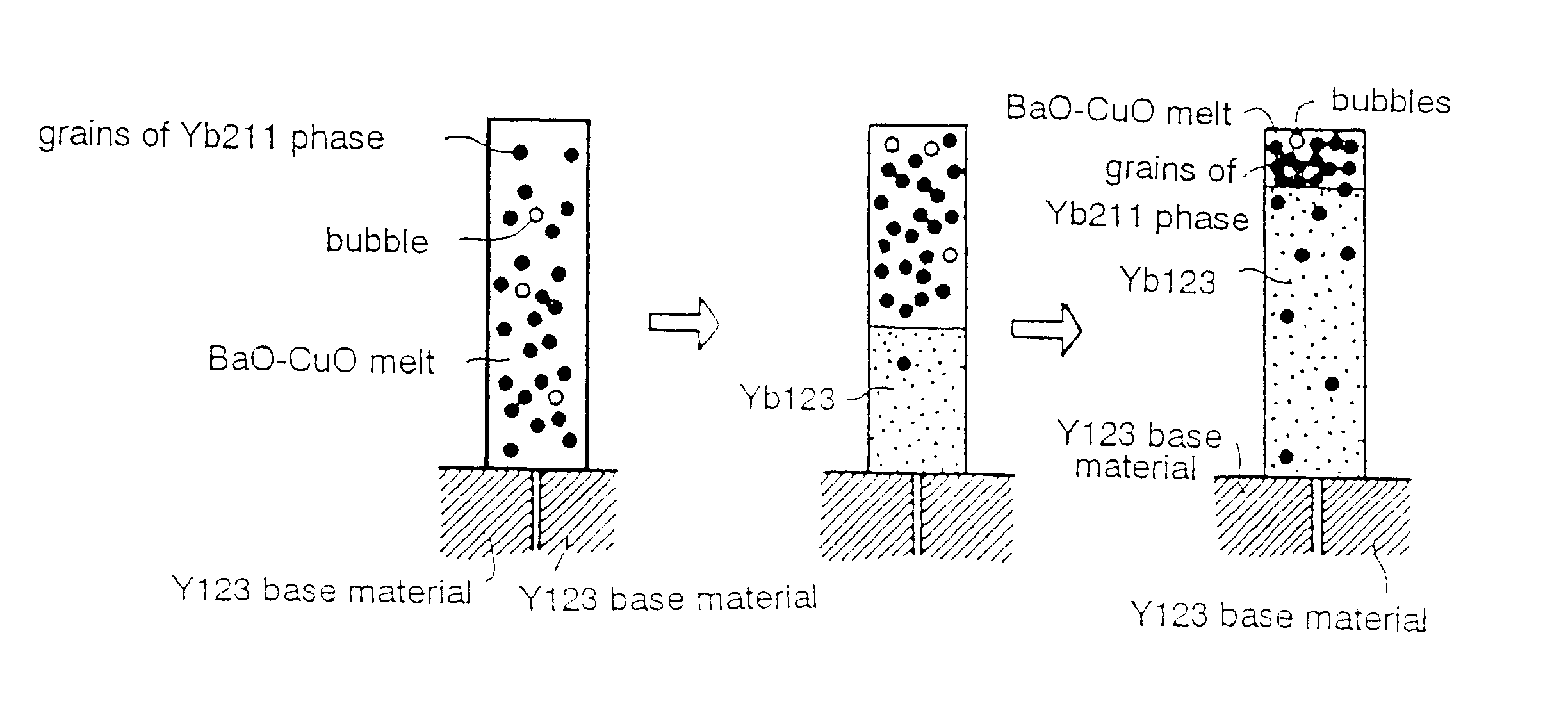
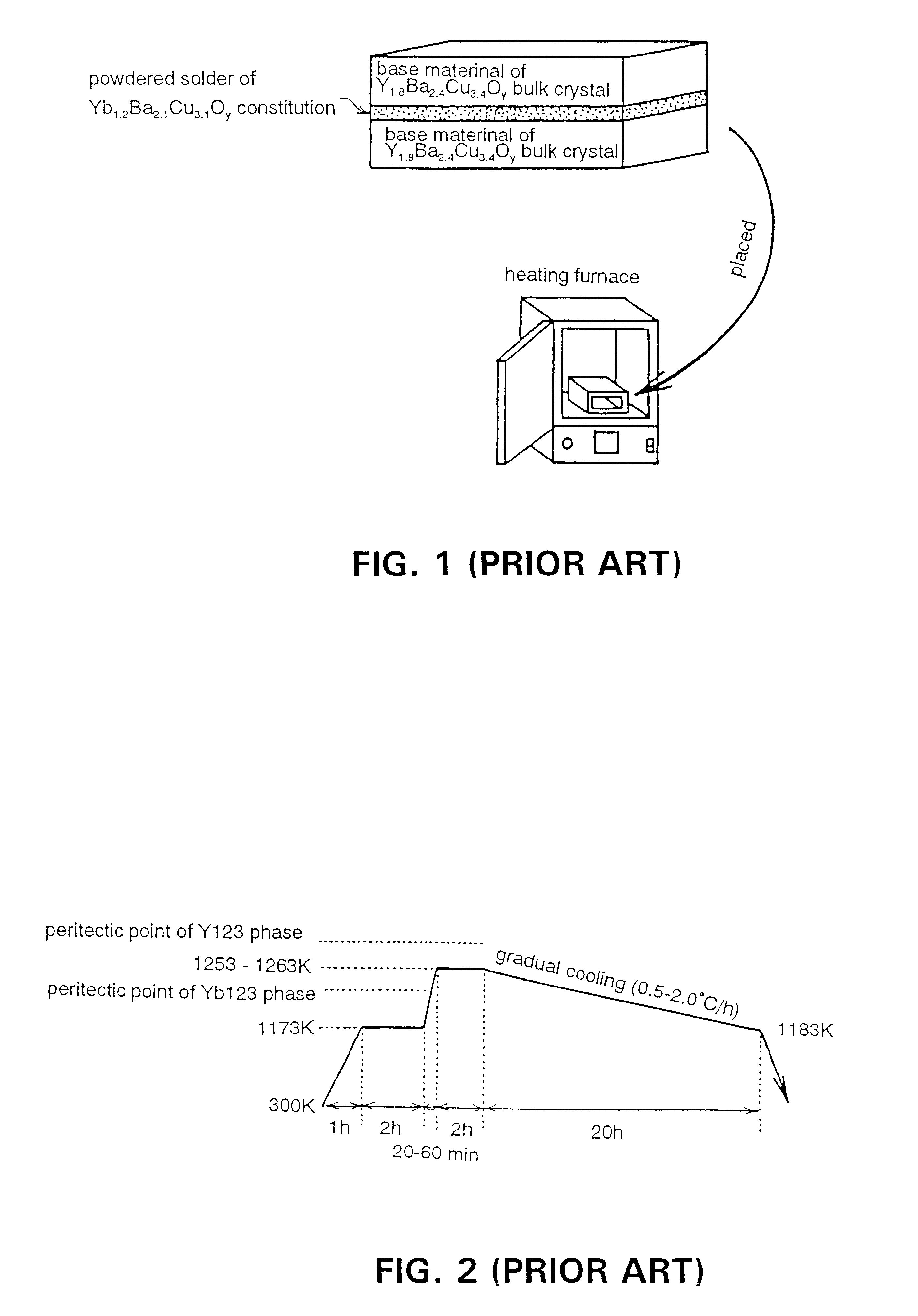
For the solder for use in a joining process, powders (powders of Yb211+Ba.sub.3 Cu.sub.5 O.sub.x) of Yb 123 superconducting material (Yb.sub.1.2 Ba.sub.2.1 Cu.sub.3.1 O.sub.y) constitution were used.

When joining together the base materials, the base materials were first laid such that a side face of one of the base materials, at one end thereof, was kept in intimate contact with a side face of another of the base materials, at one end thereof, so as to overlap each other as shown in FIG. 8, and the solder in powder form was overlaid on top of the overlapped part of the base materials so as to straddle both the b...

reference example 2

First, Nd 123 superconducting bulk crystals (NdBa.sub.2 Cu.sub.3 O.sub.y) were prepared by a melt-solidifying process.

In the next step, a square member was cut from the Nd 123 superconducting bulk crystals, respectively, by machining, and an attempt was made to join together two pieces of the square members as base materials to be joined together by use of a solder.

For the solder for use in a joining process, powders (powders of Sm 211+Ba.sub.3 Cu.sub.5 O.sub.x) of Sm 123 superconducting material (SmBa.sub.2 Cu.sub.5 O.sub.y) constitution were used.

When joining together the base materials, the respective base materials were first cleaved at one end thereof as shown in FIG. 10 (a), exposing respective cleavage surfaces (ab faces), and thereafter, a portion of the end of one of the base materials was cut off as shown in FIG. 10 (b).

Then, the end of the one of the base materials, rendered in such a condition as above, was butted at the end of the other base material as shown in FIG. 10...


PUM

PropertyMeasurementUnit
superconductingaaaaaaaaaa
superconductoraaaaaaaaaa
non-superconductingaaaaaaaaaa

Abstract

Methods for implementing production of an oxide superconductor joined member, excellent in electric current transmission performance, without a need of going through particularly complex steps, are provided. When joining together oxide superconductors by use of a solder composed of an oxide superconducting material, a finally solidified portion of the solder is positioned in a region where a transmission path of electric current flowing between oxide superconductor base materials as joined together is not obstructed by, for example, disposing the solder on a face of the oxide superconductor base materials, other than butting surfaces of the oxide superconductor base materials, so as to straddle both the base materials like bridge-building. Current flow is also not obstructed by, for example, shaping junction faces of the oxide superconductor base materials such that at least portions of the butting surfaces thereof are in the shape of sloped open faces, parting from each other. Further, an oxide superconductor joined member is made by joining the base materials with each other through the intermediary of an oxide superconductor, serving as a binder, disposed on at least a face of the base materials, other than butting surfaces thereof.

Description

1. Field of the InventionThe present invention relates to a method of joining together oxide superconductors for producing an oxide superconductor joined member having excellent electric current transmission performance, enabling electric current transmission to be effected at high efficiency, and to the oxide superconductor joined member having excellent electric current transmission performance, so that electric current lead wires and superconducting wire rods, excellent in electric current transmission performance, can be produced.2. Description of the Related ArtThere have recently been discovered oxide superconductors having high critical temperatures such as, for example, LiTi.sub.2 O.sub.3, Ba(Bi, Pb)O.sub.3, (Ba, K) BiO.sub.3, (La, Sr).sub.2 CuO.sub.4, REBa.sub.2 Cu.sub.3 O.sub.7 (RE refers to rare-earth elements), Bi.sub.2 Sr.sub.2 Ca.sub.2 Cu.sub.3 O.sub.10, Ti.sub.2 Ba.sub.2 Ca.sub.2 Cu.sub.3 O.sub.10 or HgBa.sub.2 Ca.sub.2 Cu.sub.3 O.sub.8 and so forth, one after another...

Claims


Application Information

Patent Timeline
Patent Type & Authority Patents(United States)
IPC IPC(8): H01L39/02H01B13/00B23K35/14H01B12/02
CPCH01L39/02Y10S505/918Y10S505/927Y10S505/919Y10T29/49014Y10S505/92Y10S505/917Y10S505/926Y10S505/925H10N60/80
Inventor MAEDA, JYUNYASEIKI, SUSUMUIZUMI, TERUOSHIOHARA, YUH
Owner SUPERCONDUCTIVITY RES LAB
Why Eureka
Try Eureka